


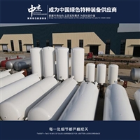
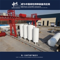

Zhejiang Liquid Nitrogen Storage Tank Safety Operation Regulations - Advantages of Zhongjie Low Temperature Storage Tank
Category:
mechanical equipment/Storage and transportation equipment/storage tank
Model:
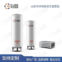
CFL10-0.8
Brand:
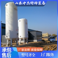
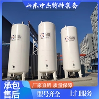
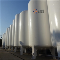
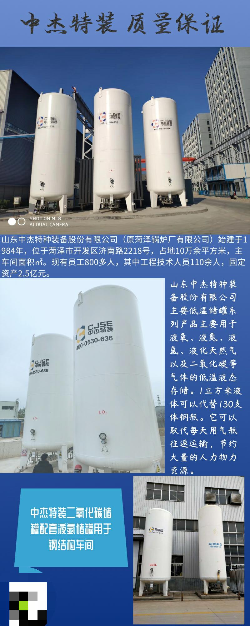
Zhongjie Special Equipment
Retail Price
125,000.00USD
重量
kg
- Product Description
-
Description :
Purpose: To establish standard operating and maintenance procedures for low-temperature liquid nitrogen storage tanks
Scope: All low-temperature liquid nitrogen storage tanks
Responsibilities: Operators, maintenance personnel, technicians, and workshop managers are responsible for the implementation of this regulation
1. Equipment flowchart
Operation of filling, supplementary filling, gas supply, low-temperature pump system, low-temperature liquid spray system, small container filling, tanker filling, pressure regulating valve setting, and liquid level meter.
2.1 Operation method for filling
2.1.1 Confirm that the liquid in the liquid supply device is the liquid to be filled.
2.1.2 Confirm that except for the upper and lower valves (V-9, V-11) of the liquid level gauge, all other valves are in the closed state.
2.1.3 Connect the infusion hose of the liquid supply device to the filling port C-1 of the storage tank.
2.1.4 Fully open valve V-13 and perform atmospheric pressure filling.
2.1.5 Open the pipeline long liquid emptying method V-3, slightly open the drain valve of the liquid supply device to cool the infusion soft tube, and at the same time blow away impurities and air at the C-1 port of the storage tank.
2.1.6 Close the residual liquid discharge valve v-3 of the pipeline, slowly open the top liquid inlet valve v-2, and perform top spray filling.
During the liquid filling process, attention should be paid to the storage tank pressure gauge P-1. If the pressure of the container in the storage tank rises above the supply pressure or close to the normal working pressure of the storage tank, the inner container vent valve V-13 should be opened to release the gas and pressure from the storage tank.
2.1.8 Use V-2 for top filling.
2.1.9 Open the residual liquid discharge valve V-3 of the pipeline, discharge the residual liquid from the infusion metal hose and the upper inlet pipe, and then close the bottom liquid inlet valve V-2 and the residual liquid discharge valve V-3 of the pipeline. Close the vent valve V-13 of the inner container.
2.1.10 Release the connection joint between the infusion hose and the filling port C-1 of the storage tank, defrost the surface of the hose, and remove the infusion hose after the hose returns to flexibility.
2.2 Supplementary charging operation method.
2.2.1 Confirm that the liquid in the liquid supply device is the liquid to be filled.
2.2.2 Confirm that except for the upper and lower valves (V-9, V-11) of the liquid level gauge, all other valves are in the closed position.
2.2.3 Open the vent valve V-13 of the inner container to release pressure. Connect the infusion hose of the liquid supply device to the installation port C-1 of the storage tank.
2.2.4 Open the residual liquid discharge valve V-3 of the pipeline and slightly open the discharge valve of the liquid supply device to cool the infusion hose, while blowing away impurities and air at the filling port C-1 of the storage tank.
2.2.5 Close the residual liquid discharge valve V-3 in the pipeline and slowly open the top liquid inlet valve V-2 to the fully open position.
2.2.6 Slowly open the bottom liquid inlet and outlet valve V-1 to simultaneously fill the top and bottom.
During filling, attention should be paid to the storage tank pressure gauge P-1.
2.2.8 Open the residual liquid discharge valve V-3 of the pipeline, discharge the residual liquid in the infusion metal hose and the upper inlet pipe, semi close the top V-2 and V-3, and then close V-13.
2.2.9 Release the connector between the infusion hose and the filling port C-1 of the storage tank, defrost the surface of the hose, and remove it after the hose returns to normal.
2.3 Operation method of gas supply
2.3.1 Confirm that all valves except for the upper and lower valves (V-9, V-11) of the liquid level gauge are closed.
2.3.2 Open the return valve V-6, the additional valve V-5, and the liquid outlet valve V-7 in sequence.
2.3.3 When the required amount of gas has been output, or when the storage tank needs to be closed without stopping gas delivery for a long time, close the liquid outlet valve V-7, increase the valve opening, and after 15-20 minutes, close the return valve V-6.
2.4 Operation method for low-temperature pump liquid supply
2.4.1 Confirm that all valves except for the upper and lower valves (V-9, V-11) of the liquid level gauge are in the closed position.
2.4.2 Open the return valve V-6 and the additional valve V-5 in sequence. According to the operating procedures of the low-temperature liquid pump, open the pump inlet valve and pump return valve, start the low-temperature liquid pump, and the outlet end of the low-temperature liquid pump will output high-pressure low-temperature liquid. After passing through the vaporizer, it enters the inflation system and can be used to deliver high-pressure gas and fill high-pressure gas cylinders.
2.4.3 The storage tank will automatically deliver low-temperature liquid at a constant pressure to the inlet end of the low-temperature pump according to the user's set pressure.
2.4.4 At the end of gas filling, close the low-temperature pump according to the operating procedures of the low-temperature pump, and close the inlet end and pump return valve.
2.4.5 Close the additional valve V-5 of the storage tank, and then close the return valve V-6 after 10-20 minutes.
2.5 Operation method of low-temperature liquid spray system
2.5.1 Confirm that except for the upper and lower valves (V-9, V-11) of the liquid level gauge, all other valves are in the closed position. Open the return valve V-6 and add V-5 in sequence.
2.5.2 Open the valve supplying liquid to the low-temperature liquid spray system and start delivering low-temperature liquid to the low-temperature liquid spray system.
After the low-temperature spray system is completed, close the valve that supplies liquid to the low-temperature liquid spray system from the storage tank. Close the additional valve V-5 of the storage tank, and then close the return valve V-6 after 10-20 minutes.
2.6.1 Connect V-4 to the small container using a rubber tube or metal pipe (such as copper tube or metal hose). Open the vent valve.
2.6.2 Slowly open the small container filling valve V-4. The filling process should be smooth to prevent low-temperature liquid splashing. After the small container is filled, close the small container filling valve V-4.
2.7 Operation method for filling low-temperature liquid from storage tank to tanker:
2.7.1 Confirm that the low-temperature liquid in the storage tank is the medium to be filled into the tanker.
2.7.2 Confirm that all valves in the storage tank, except for pressure gauge V-12 and level gauge upper and lower valves (V-9, V-11), are in the closed position.
2.7.3 Connect the filling port C-1 of the storage tank to the filling port of the tanker using an infusion hose.
2.7.4 Open the return valve V-6 and the additional valve V-5, and the container in the storage tank begins to increase pressure, which is lower than the working pressure of the storage tank.
2.7.5 Open the bottom liquid inlet and outlet valve V-1 to start infusion into the tanker. Follow the operating procedures for filling the tanker with low-temperature liquid and correctly operate the valve and pipeline system of the tanker to fill with low-temperature liquid.
2.7.6 After the tanker is filled, immediately close the liquid inlet and outlet valve V-1 at the bottom of the storage tank.
2.7.7 Close the storage tank valve V-5, and after 5-6 minutes, close the return valve V-6.
2.7.8 Open the residual liquid discharge valve V-3 of the storage tank pipeline, release the gas-liquid in the infusion hose, and remove the infusion hose after the hose returns to flexibility. Operation completed.
2.8 Operation method of boost control valve R-1:
2.8.1 Determine the set pressure of the boost control valve R-1.
2.8.2 Confirm that all valves in the storage tank, except for the upper and lower valves (V-9, V-11) of the liquid level gauge, are closed.
2.8.3 Adjustment of pressure setting for pressure boosting regulating valve R-1. Observe the reading of pressure gauge P-1. If the pressure is higher than the set pressure of the boost control valve R-1, close the booster valve V-5 and open the inner container vent valve V-13. When the pressure is equal to the set pressure of R-1, close the inner container vent valve V-13. If the pressure is lower than the set pressure of the regulating valve R-1, tighten the regulating screw of R-1 to slowly increase the storage tank force; When the storage tank pressure is equal to the set pressure of R-1, close the additional valve V-5.
2.8.4 When the temperature of the additional valve V-5 and the pressure increasing regulating valve R-1 rises to ambient temperature, loosen the adjusting screw of the pressure increasing regulating valve R-1 outward and place it in the closed state.
2.8.5 Open the booster valve V-5 in small increments, tighten the adjusting screw of R-1, and stop the adjusting screw of R-1 when the booster regulating valve R-1 is opened. And tighten the adjusting screw of R-1.
2.8.6 Review the set pressure of R-1. Open the vent valve V-13 of the inner container to reduce the pressure in the storage tank; When the pressure drops to 0.1MPA below the set pressure of the pressure regulating valve R-1, close the vent valve V-13 of the inner container. Slightly open valve V-5; The pressure in the storage tank gradually increases; Observe the pressure gauge P-1 and the pressure regulator R-1. If the pressure of the inner container stabilizes at the pressure required by P-1, the set pressure adjustment work of the pressure increasing regulating valve RT-1 is completed.
3.1 Security maintenance; Due to liquid nitrogen being a flammable and explosive gas, smoking, open flames, and open flames are strictly prohibited within 6 meters of liquid oxygen equipment. At the same time, static sparks should be avoided during operation. If maintenance operations are required, they must be carried out under the supervision of the company's security department. Workers must wear appropriate protective equipment during operation to prevent low-temperature liquids from coming into contact with the skin and eyes.
3.2.1 Check whether all valves are in the open and closed state.
3.2.2 Check if the liquid level gauge and pressure gauge are normal.
3.2.3 Check for leaks and blockages in pipelines, joints, and valves.
3.2.4 Check if the storage tank pressure is normal. When the storage tank pressure approaches or equals the working pressure, the inner cylinder vent valve V-13 must be opened to release pressure.
3.2.5 Check the calibration of pressure gauges, liquid level gauges, and safety opening valves every 2 years, and replace the bursting disc of the inner cylinder blasting device every year.

AfterSalesService :
Key words:- Safety Operating Procedures for Liquid Nitrogen Storage Tanks
More Products


