


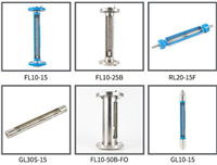

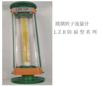

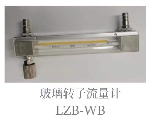
Flange connected anti-corrosion glass rotor flowmeter
Category:
Instrumentation/Flow meter/Rotameter
Model:
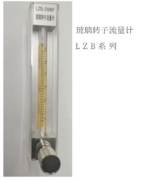
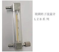
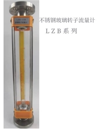
LZB
Brand:
Xinwang
brand:
Xinwang
model:
LZB
connection method:
Threaded type
measurement range:
10-100L/MIN
accuracy class:
2.5, 1.5
Nominal Diameter:
dn10-1000
Operating Temperature:
-40℃~+350℃
display mode:
On site display
Applicable Medium:
Strong acids, strong bases, oxidants, organic solvents, corrosive gases, liquids, nitric acid, sulfuric acid, hydrochloric acid, acetone
material:
304 stainless steel and PTFE material
Processing & Customization:
yes
Whether it is imported:
No
Overall dimensions:
one hundred and thirty-six
Place of Origin:
Jiangsu
manufacturer:
Xinwang Instrument
Retail Price
150.00USD
重量
kg
- Product Description
-
brand Xinwang
model LZB
connection method Threaded type
measurement range 10-100L/MIN
accuracy class 2.5, 1.5
Nominal Diameter dn10-1000
Operating Temperature -40℃~+350℃
display mode On site display
Applicable Medium Strong acids, strong bases, oxidants, organic solvents, corrosive gases, liquids, nitric acid, sulfuric acid, hydrochloric acid, acetone
material 304 stainless steel and PTFE material
Processing & Customization yes
Whether it is imported No
Overall dimensions one hundred and thirty-six
Place of Origin Jiangsu
manufacturer Xinwang Instrument
Description :
Glass rotor flow meters are mainly used in various departments such as chemical, petroleum, light industry, medicine, fertilizer, synthetic fiber, food, dye, environmental protection, and scientific research to measure the flow rate of single-phase non pulsating (liquid or gas) fluids. The corrosion-resistant glass rotor flowmeter is mainly used for detecting the flow rate of corrosive liquids and gas media, such as strong acids (excluding), strong bases, oxidants, strong oxidizing acids, organic solvents, and other corrosive gas or liquid media.
select
1. Object of measurement. Measure the type of medium, pressure level, and chemical properties. For corrosive media such as liquid and gas media, corrosion-resistant flow meters should be selected.
2. The performance of the flowmeter itself. After the above conditions are determined, generally speaking, if there is no significant change in price, priority can be given to using a needle valve placed on the upper part of the flowmeter; For those with larger flow holes, it is a direct flow scale; Simple in structure; Smaller external dimensions, etc. If it is in a small flow range, the ball float type can be used because it is stable, less prone to dust accumulation, has high accuracy, and has good interchangeability during measurement.
3. Choose according to the price. Generally speaking, high precision comes at a higher price. The accuracy level of the instrument should be selected according to the measurement purpose. If only the measurement medium throughput needs to be controlled, adjusted through trial operation, and the throughput needs to be consistently stable in the future, then accuracy is secondary.
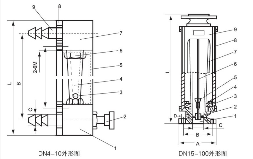
When the fluid flows through the conical tube from bottom to top, the lift S generated by the kinetic energy of the fluid on the float and the buoyancy A of the fluid cause the float to rise. When the sum of the lift S and buoyancy A is equal to the weight G of the float itself, the float is in equilibrium and stable at a certain height position. The scale on the conical tube indicates the flow rate value of the fluid.
Install and use voice editing
How to choose a glass rotor flowmeter correctly
The glass rotor flowmeter is a simple to use, easy to read, and widely used instantaneous flow measurement instrument. In the field of environmental protection equipment and instruments, the usage reaches over 30000 units per year. Therefore, it is extremely important to choose and use this instrument well.
Types and selection of glass rotor flow meters
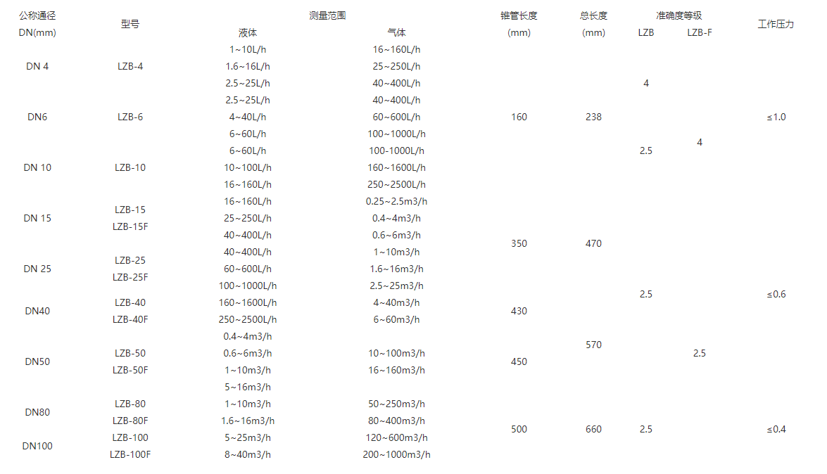
Glass rotor flow meters can be divided into eight series based on their applications and adaptability: ordinary type, reinforced pipe type, small flow and small shape type, corrosion-resistant type, laboratory type, insulation type, alarm type, and high-pressure resistant type. According to the national instrument series spectrum, regardless of which series, there are a maximum of 12 calibers ranging from 1 millimeter to 100 millimeters. The measurable flow range is: 0.1 milliliter/minute to 40 cubic meters/hour for liquid (water) and 1 milliliter/minute to 1000 cubic meters/hour for gas (air). The glass rotor flowmeter used for environmental protection instruments generally has a diameter of no more than 10 millimeters, and the measured flow rate belongs to the small flow range.
Calibration correction of glass rotor flowmeter
The scale of the glass rotor flowmeter is calibrated by the manufacturer using water and dry air, which are close to ideal fluids, as the medium under local conditions. But in the use of flow meters, there are two situations where their scale values cannot be directly used: one is when the measuring medium is not water and air, and the other is when the measuring medium is water and air, but its state (temperature, pressure) is different from the scale state. In this way, when using a flow meter, there is a problem of needing to correct the scale values in order to obtain accurate measurement results. Therefore, solving the calibration correction of glass rotor flow meters is the key to using this type of instrument effectively.
Considering the extensive use of rotor flow meters in environmental instruments for measuring gas medium flow, the following discussion will only focus on density correction during gas medium measurement. Due to the low viscosity of gas media, the influence of viscosity is omitted in the discussion. Practice has proven that this does not affect the accuracy after correction.
The following is the general expression for the flow rate of a rotor flowmeter
Equation (1) is a calculation formula that does not consider the influence of medium viscosity. From equation (1), it can be clearly concluded that when the height of the float position of a flowmeter is determined, the density of the measured medium ρ is a variable. If the density of the measured medium is different, the flow rate of the medium through the flowmeter will also be different. Therefore, scale correction is actually flow correction.
If two media with different densities ρ 1 and ρ 2 pass through the same rotor flowmeter, and the float is balanced on the same solid, the basic formula for converting the density of the rotor flowmeter can be obtained from equation (1):
In the formula, P1 and Tl, as well as P2 and T2, are two states of the same medium represented by pressure and temperature parameters, respectively. It can be seen that for the same gas medium, its density conversion can be completely converted into temperature and pressure conversion under different states. In this way, for the calibration correction of measuring the flow rate of the same gas medium, it ultimately becomes a state correction of temperature and pressure (essentially density correction). It is obvious that this is a correction method that is easily achievable using units.
(1) How to obtain the actual flow rate value from the scale reading of the flowmeter on site?
The purpose of using ready-made applications for flow meters is only one: to detect the actual flow rate of the measured medium. However, many users ignore the difference between the on-site state and the scale state of the flowmeter (i.e. standard state), and directly use the scale reading of the flowmeter as the actual flow value of the measured medium. It is very obvious that this actual flow rate is not true, which will bring errors to the measurement of the flowmeter and cause errors in the detection results of the supporting instruments.
On site, obtaining the actual flow rate value from the scale reading of the flowmeter is essentially converting the flow rate value under the standard state of the flowmeter into the flow rate value under the on-site operating conditions. We set the parameter codes related to the on-site working conditions as actual flow rate Q, medium pressure P, and temperature T; the parameter codes related to the scale of the rotor flowmeter are flow rate Q, pressure Po compared to the standard state, and temperature To. According to equation (4):
By using equation (5), it can be seen that it is very convenient to obtain the actual flow rate value of the measured medium from the flowmeter reading on site. It should be noted that when using equation (5) for calculation, P、P。 、 T、T。 All values should be inputted, and P is the pre gauge pressure, which should be measured on the upstream side of the flowmeter and adjacent to the pipeline of the flowmeter.
Example: Using a certain air sampling device, during operation, the reading of the rotor flow meter on the sampling device is 500 milliliters per minute, the pressure in front of the measuring instrument is -100mmH 20 (negative pressure due to the use of an air pump), and the on-site temperature is 30 ℃. Calculate the actual flow rate of air at this time.
According to the measured data, there are
Here, because P. is measured in millimeters of mercury, the millimeter water column must be converted into millimeters of mercury. When calculating, simply divide the millimeter water column by 13.6.
From the above example results, it can be seen that although the on-site state is not significantly different from the standard state, there is a difference of 22 milliliters per minute (4.4% of the standard value) in the measurement results. In other words, if the route is not corrected, there will be a 4.4% error in the flow value!
(2) How can users choose a suitable rotor flowmeter based on their actual usage flow?
This problem is exactly the inverse process of (1) above. Simply reverse equation (5) to obtain:
Here, Q is the actual usage of traffic; P. T, Po, and To are all known, and Qn calculated using equation d in [6] is the calibrated flow rate value of the rotor flowmeter to be selected. Note that Q should be the commonly used traffic. To ensure sufficient accuracy and margin when using the flow meter, the upper limit for selecting a glass rotor flow meter should be 1.5 times Qn.
We want to emphasize the importance of this clause because it cannot be ignored when the pressure of the measured medium is high. For example, if the pressure of the measured medium is 3kg/cm2 and it is assumed that the temperature is almost the same as the standard temperature, then P=3+1kg/cm2 (unit:, P。=1), After substituting into equation (6), Qn ÷ 2Q will be obtained. That is to say, if the commonly used flow rate is Q, the appropriate upper limit of the flow meter should be 1.5 × 2 Q=3Q. If the flow meter is still selected according to Q, it will not meet the usage requirements and delay production.
The density conversion of the rotor flowmeter can also be performed using the graphical method.
The calibration correction when measuring liquid media often involves viscosity correction, which is very complex and difficult to calculate. However, there are other ways to make up for it, which will not be elaborated here due to space limitations.

AfterSalesService :
Key words:- Glass rotor flowmeter


