


Manufacturer of liquid gas natural gas rod type glass rotor flowmeter
Category:
Instrumentation/Flow meter/Rotameter
Model:
FA100
Brand:
Xinwang
brand:
Xinwang
model:
FA100
connection method:
flange connection
measurement range:
10-100L/MIN
accuracy class:
2.5, 1.5
Nominal Diameter:
Flow rate 10-100L/MIN
Operating Temperature:
Room temperature 20
work pressure:
0.2-0.7
display mode:
On site display
Applicable Medium:
Strong acids, strong bases, oxidants, organic solvents, corrosive gases, liquids, nitric acid, sulfuric acid, hydrochloric acid, acetone
turndown ratio:
1:10
material:
304 stainless steel and PTFE material
Processing & Customization:
yes
Whether it is imported:
No
Overall dimensions:
three hundred and twenty
Place of Origin:
Jiangsu
manufacturer:
Xinwang Instrument
Retail Price
850.00USD
重量
kg
- Product Description
-
brand Xinwang
model FA100
connection method flange connection
measurement range 10-100L/MIN
accuracy class 2.5, 1.5
Nominal Diameter Flow rate 10-100L/MIN
Operating Temperature Room temperature 20
work pressure 0.2-0.7
display mode On site display
Applicable Medium Strong acids, strong bases, oxidants, organic solvents, corrosive gases, liquids, nitric acid, sulfuric acid, hydrochloric acid, acetone
turndown ratio 1:10
material 304 stainless steel and PTFE material
Processing & Customization yes
Whether it is imported No
Overall dimensions three hundred and twenty
Place of Origin Jiangsu
manufacturer Xinwang Instrument
Description :
Overview:
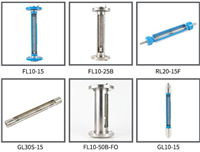
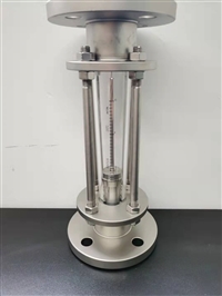
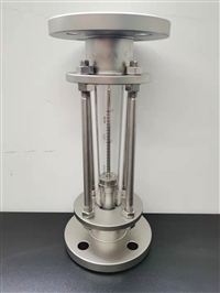
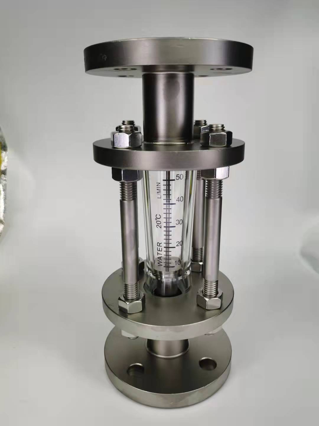
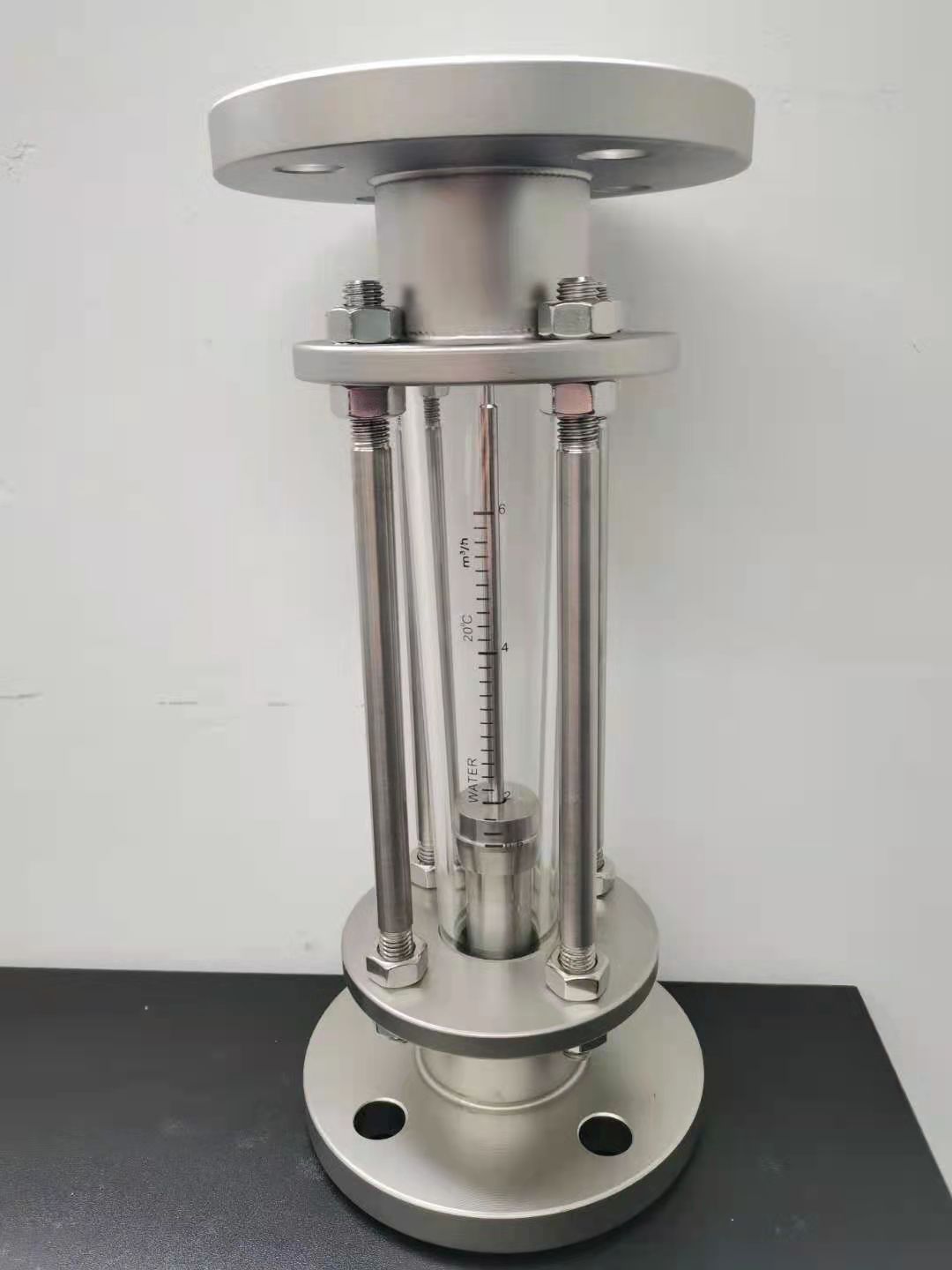
The LZB-FA100 series flowmeter is a type of glass rotor flowmeter. It has the characteristics of high sensitivity, wide measurement range, and easy use and maintenance. The connection method of the instrument is flange connection. The LZB-FA100 series glass rotor flowmeter is used to measure non turbid and non pulsating liquid or gas flow under constant pressure conditions by utilizing changes in the flow cross-section.
The LZB-FA100 series glass rotor flowmeter is widely used in petroleum, chemical, metallurgical, synthetic fiber, dye, papermaking, environmental protection equipment, food, sugar, and scientific experimental instrument supporting facilities.
Two principles and structure:
The main measuring components of the LZB-FA100 series glass rotor flowmeter instrument are a vertically installed conical glass tube (referred to as the cone tube) with a small end facing downwards and a large end facing upwards, and a float that can move up and down inside. When the fluid flows through the conical tube from bottom to top, a pressure difference is generated between the floats, and the floats rise under this pressure difference. When the lift force of the float is equal to the combined force of gravity, buoyancy, and viscosity, the float is in an equilibrium position. Therefore, there is a certain proportional relationship between the flow rate of the fluid flowing through the glass rotor flowmeter and the rising height of the float, that is, the fluid area of the instrument. The height of the float position can be used as a measure of the flow rate.
The reading of the instrument should be taken at the reading position shown in Figure 1.
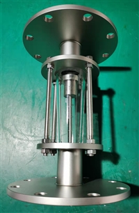
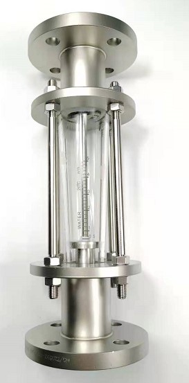
The tolerance diameter of LZB-FA100 series glass rotor flowmeter includes φ15,φ20,φ25,φ32,φ40,φ50,φ65,φ80,φ100,φ125,φ150, Among them, diameter 125 and diameter 150 are customized versions, connected by flange connection, and the structure is shown in Figure 2
The external installation dimensions of LZB-FA100 are shown in Table 1
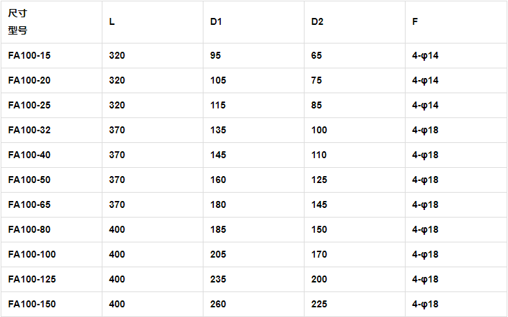 Three technical parameters: Table 1
The main technical parameters of LZB-FA100 glass rotor flowmeter are shown in Table 2
path
(mm)
measurement range
work pressure
(Mpa)
precision
(±%)
Water (L/H)
Air (NL/min)
fifteen
30~300
60~600
80~800
10~100
20~200
25~250
≤0.8
four
twenty
90~900
120~1200
180~1800
20~200
30~300
50~500
two point five
twenty-five
180~1800
300~3000
480~4800
50~500
100~1000
150~1500
thirty-two
480~4800
600~6000
720~7200
200~2000
250~2500
300~3000
forty
1~10 m3/H
1.2~12 m3/H
1.5~15 m3/H
18~180N m3/H
20~200 Nm3/H
25~250N m3/H
≤0.6
fifty
1.2~12 m3/H
1.5~15 m3/H
1.8~18 m3/H
20~200 Nm3/H
25~250N m3/H
30~300 N m3/H
sixty-five
1.8~18 m3/H
3~30 m3/H
4~40 m3/H
25~250N m3/H
30~300 N m3/H
40~400 N m3/H
one point five
eighty
4~40 m3/H
5~50 m3/H
6~60 m3/H
40~400 N m3/H
50~500 N m3/H
60~600 N m3/H
≤0.4
one hundred
one hundred and twenty-five
one hundred and fifty
6~60 m3/H
7~70 m3/H
10~100 m3/H
60~600 N m3/H
70~700 N m3/H
90~900 N m3/H
Note: Special flow rates and sizes can be customized according to customer requirements
Table 2
Four installations:
Open the box of the FA100 series glass rotor flowmeter, check for accuracy, remove the filling material, and install it vertically (the angle between the instrument centerline and the lead wire should not exceed 5 °) on a vibration free pipeline with correct support to prevent stress from entering.
4.2 Newly installed pipelines should be flushed clean before instrument installation. When installing the glass rotor flowmeter into the pipeline, the minimum division value on the cone tube should be below.
4.3 In order to facilitate maintenance, sufficient space should be left around the instrument. The bypass pipe must be installed according to the diagram.
4.4 Valves should be installed upstream of the instrument, and throttling valves should be installed 5-10D downstream. If there is backflow or water hammer damage to the glass cone tube of the glass rotor flowmeter in the pipeline, a one-way check valve should be installed after the downstream valve.
4.5 If the measured fluid contains large particles, impurities, or bubbles, a filter or exhaust port should be installed upstream of the instrument.
4.6 If the fluid being measured is a pulsating flow, causing the float to be passive and unable to measure correctly, a buffer and setting device of appropriate size should be installed downstream of the glass rotor flowmeter to eliminate pulsation.
Five uses, maintenance:
5.1 When using a glass rotor flowmeter, the upstream valve should be slowly opened to full open, and then the flow rate should be adjusted using the downstream regulating valve of the instrument. When the glass rotor flowmeter stops working, the upstream valve should be slowly closed first, and then the regulating valve of the glass rotor flowmeter should be closed.
5.2 When using a glass rotor flowmeter, sudden changes in the measured fluid pressure should be avoided.
The flow reading of the glass rotor flowmeter should be read along with the float reading shown in Figure 1.
If the working diameter (reading edge) of the glass rotor flowmeter is damaged, it should be recalibrated.
During the use of the 5.5 glass rotor flowmeter, if leakage is found, the cover bolts should be evenly tightened to avoid over tightening and crushing the cone tube
During the use of the 5.6 glass rotor flowmeter, if the gland is tightened but still leaks, it is generally due to the failure of the sealing material, and the sealing material should be replaced.
5.7 If the cone tube and float of the glass rotor flowmeter are contaminated, they should be cleaned in a timely manner to avoid reducing accuracy.

AfterSalesService :
Key words:- Glass rotor flowmeter


