


Fire certification switch quantity smoke sensing quotation JTY-GD-S832
Category:
Security/Public Address System/Public Address System
Model:
JTY-GD-S832
Brand:
Hongsheng High Tech
Retail Price
0.99USD
重量
kg
- Product Description
-
Description :
1、 Overview
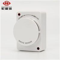
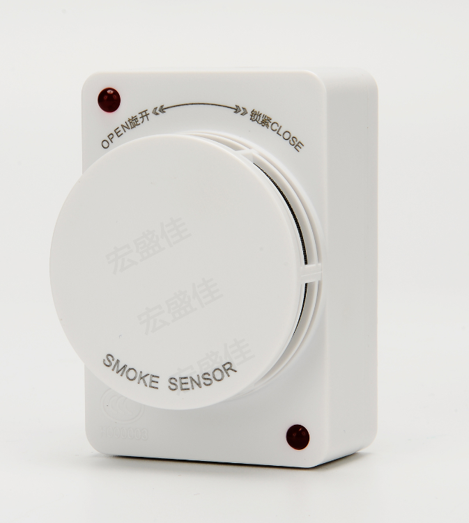
JTY-GD-S832 Point type photoelectric smoke fire detector (hereinafter referred to as the detector, as shown in the picture) one As shown, it adopts a non-polar power input, which can detect the smoke generated during a fire and issue an alarm signal in a timely manner. explore The measuring device adopts CPUControl, capable of intelligently determining the concentration of smoke generated during a fire. The detector is under surveillance When in state, the red indicator light flashes and the working current is low; When the smoke concentration on site exceeds the set alarm threshold, The detector enters an alarm state, with the red indicator light constantly on and the relay activated. The detector is equipped with a relay Contact output, alarm signal is given in the form of relay contact action changes, and has alarm locking function, The reset of the alarm can only be achieved through a brief power outage. The detector has an automatic compensation function for dust accumulation, which can reduce The impact of less dust on detector sensitivity. The detector is suitable for places where a large amount of smoke is generated during a fire, but there is no smoke under normal circumstances, For example, industrial facilities such as restaurants, hotels, teaching buildings, office buildings, computer rooms, communication rooms, bookstores, and archives Regarding civil buildings. But not suitable for places with a large amount of dust and water mist retention; Not applicable for potential steam generation Places with oil mist; Not suitable for places with smoke retention under normal circumstances
2、 Characteristics and technical indicators
1. Implementation standard: GB4715-2005
2. Working voltage: DC12V/24V (allowable range 9V~30V)
3. Working current: Monitoring status< 1mA@DC12V <5mA @ DC24V fire alarm< 30mA@DC12V <35mA @DC24V
4. Relay output: normally open (closed after fire alarm), contact capacity 1 A 30VDC
5. Work instructions: The red indicator light for monitoring status flashes approximately every 6 seconds; The red indicator light for alarm status is always on; The red indicator light for fault status flashes continuously twice every 6 seconds
6. Operating environment: Temperature: -10 ℃ to+65 ℃,
Relative humidity: ≤ 95% (40 ℃± 2 ℃ without condensation)
7. Dimensions: 75mm × 51.8mm × 38.5mm (with base),
III. Installation and Debugging
Determine the installation position, spacing, and quantity of detectors in the protected area in accordance with the relevant provisions and requirements of standard GB50116-98.
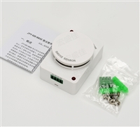
The installation of the detector requires the use of a matching base. The supporting base is shown in Figure 3, with dimensions of 75mm × 51.8mm × 5mm (length × width × height), fixing holes of 5mm × 10mm, and a spacing of 52mm to 66mm between fixing holes. The detector is connected to the outside world through 4PIN plug-in terminals (see Figure 4), where D1
Pin D2 is the power input port; K1 and K2 pins are relay output ports.
The specific methods for installation and debugging are as follows: 1. The base installation can be carried out in the following ways:
1) According to the construction drawings, use 2 M4 screws to fix the matching base in the designated position through the A and B fixing holes shown in Figure 3, and confirm that the base is securely installed; 2) According to the construction drawings, drill a ф 6mm hole at the designated location, insert the attached plastic expansion plug, and use 2 ST3.5 × 20mm self tapping screws to fix the matching base on the expansion plug through the A and B fixing holes shown in Figure 3; 3) Insert the designated magnetic steel into the fixing holes A and B shown in Figure 3, and assemble the base with the detector,
The detector is attached to the metal cabinet through magnetic steel, and this installation method is optional. 2. Cut off the power supply of the controller, connect all bases correctly according to the construction drawings, and then connect the corresponding input ports of the controller;
3. Confirm that the detector type matches the type indicated on the construction drawings;


AfterSalesService :
Key words:- Fire certification switch quantity smoke sensing quotation


