


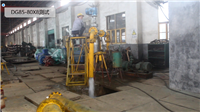


DG85-80X8 boiler feedwater pump
Category:
mechanical equipment/pump/centrifugal pump
Model:
DG85-80
Brand:
other
Retail Price
82,000.00USD
重量
kg
- Product Description
-
Description :
DG85-80X8 Product Overview
This type of pump is a horizontal multi-stage single suction segmental centrifugal pump, and the pump casing can be disassembled axially at the axis. The DG85-80 × 8 pump has a vertical upward suction inlet and a vertical upward discharge outlet, perpendicular to the axis. From the direction of the drive end, the water pump rotates clockwise. According to user needs, it can also be produced to rotate counterclockwise. Users can specify this when placing an order.
The pump body and pump cover form the working chamber of the impeller, and there are pipe screw holes for installing vacuum and pressure gauges on the inlet and outlet flanges. The lower part of the pump body has pipe screw holes for discharging residual water.
The impeller is a single suction closed type, equipped with a balance plate to balance the majority of axial forces, and a thrust bearing to withstand the possible residual small amount of axial thrust. The arrangement of the bearings keeps the shaft in a stable pulling rod state. Before assembly, the impeller must undergo strict static balance verification to ensure smooth operation.
The pump shaft is supported by two Babbitt alloy sliding bearings, which are installed in the bearing body of the pump suspension and lubricated with thin oil.
A sealing ring is installed on the pump body, which can improve the volumetric efficiency of the pump and prevent high-pressure water from flowing back into the suction chamber, disrupting the inlet flow field and ensuring the suction performance of the water pump.
The shaft seal is generally a soft packing seal. When the water pump is working, a small amount of medium can be introduced to the packing box, or external cooling and lubricating water can be connected to serve as a water seal and cooling and lubricating function. According to the user's needs, the packing seal can be changed to a mechanical seal.
Product parameters and performance parameters:
Flow rate Q 6.3-850m3/h
Lift H 75-1800m
performance parameters
D/DG/DF/MD(P)6-25 D/DG/DF/MD(P)6-50 D/DG/DF/MD(P)6-80 D/DG/DF/MD(P)12-25 D/DG/DF/MD(P)12-50 D/DG/DF/MD(P)12-80 D/DG/DF/MD(P)25-30 D/DG/DF/MD(P)25-50 D/DG/DF/MD(P)25-80 D/DG/DF/MD(P)46-30 D/DG/DF/MD(P)46-50 D/DG/DF/MD(P)46-80 D/DG/DF/MD(P)85-45 D/DG/DF/MD(P)85-67 D/DG/DF/MD(P)85-80 D/DG/DF/MD(P)85-100 D/DG/DF/MD(P)120-50 D/DG/DF/MD(P)120-100 D/DG/DF/MD(P) D/DG/DF/MD(P) D/DG/DF/MD(P) D/DG/DF/MD(P) D/DG/DF/MD(P) D/DG/DF/MD(P) D/DG/DF/MD(P)200-50 D/DG/DF/MD(P)200-100 D/DG/DF/MD(P)200-150 D/DG/DF/MD(P)210-70 D/DG/DF/MD(P)280-43 D/DG/DF/MD(P)280-65 D/DG/DF/MD(P)280-95 D/DG/DF/MD(P)280-100 D/DG/DF/MD(P)300-45 D/DG/DF/MD(P)360-40 D/DG/DF/MD(P)360-60 D/DG/DF/MD(P)360-95 D/DG/DF/MD(P)450-60 D/DG/DF/MD(P)450-95 D/DG/DF/MD(P)500-57 D/DG/DF/MD(P)550-50 D/DG/DF/MD(P)580-60 D/DG/DF/MD(P)640-80 D/DG/DF/MD(P)720-60 D/DG/DF/MD(P)1100-85 The main components of the pump are made of:
Inlet and outlet sections: ZG230-450
Mid section: ZG230-450
Guide vane: QT450
Impeller: QT450
Spindle: 40Cr
Sealing ring: QT450
Shaft sleeve: HT250
Balance disk: ZG2Cr13
Balance ring: Tin bronze
Installation steps for DG type sub high pressure boiler feedwater pump:
1.1 Preparation work
Before assembly, all pump parts, especially the precision machined surfaces that cooperate with each other, must be thoroughly cleaned.
1.1.2 Count all parts and classify and number them according to the assembly order.
1.2 Assembly of pump components
1.2.1 Pay attention to installing the middle sealing ring to prevent it from falling off.
1.2.2 Pay attention to the anti rotation pin of the guide vane.
1.2.3 Tighten the pump body through the rod nut proportionally to maintain appropriate tension. If it is too loose, it will cause leakage at the middle joint surface, and if it is too tight, it will cause deformation of the stator components. The torque of the wrench during assembly is about 5550 Nm. Tighten the cross bar according to the scale.
1.2.4 After the threaded rod is basically tightened, use a dial gauge to find that the front and rear sections are not parallel and should be ≤ 0.1mm. 1.3 Measure the total amount of rotor string, which should meet the requirements of the drawing.
1.4 Install the front cover and low-pressure end cover bearings and lower tiles, and lift the shaft to the center position.
1.5 Use specialized lifting tools and dial gauges to check the end face runout of the balance sleeve, which should meet the requirements of the final assembly drawing.
1.6 Assemble rotor components and tighten locking nuts. The measurement of the string after installing the balance plate should meet the requirements of the final assembly drawing.
1.7 Install the head and tail covers at both ends, the bearing body, and the top and side clearances of the bearing shell, which should meet the specified values for the quality requirements of the bearing shell.
Adjust the center of the bearing shells on both sides and tighten the adjusting nuts after adjustment.
1.9 Assembly of thrust bearings
1.9.1 The assembly of thrust bearing components should be scraped and ground according to the requirements of the bearing components, and the thrust pad should rotate flexibly during assembly. 1.9.2 After installing the thrust bearing, the axial clearance between the balance plate and the balance sleeve should be 0.04-0.08mm according to the requirements of the final assembly drawing, and the adjustment of the clearance should be achieved using an adjusting ring.
After adjusting the clearance, install the thrust bearing and thrust disc, and tighten the locking nut.
Adjust the gap cushion between the thrust bearing seat and the thrust plate to ensure that the final assembly drawing meets the requirements for the clearance of the thrust bearing.
AfterSalesService :
Key words:- boiler feed pump

