
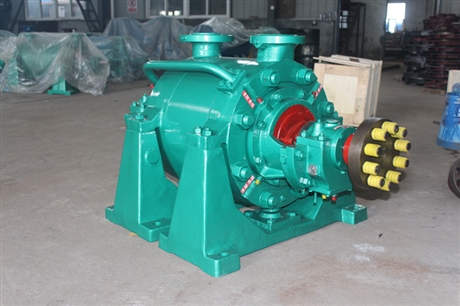

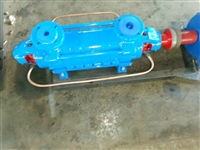
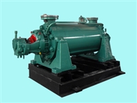
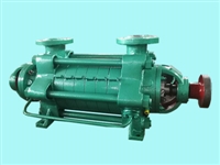

Multi stage pump DG150-30 * 7 feed pump
Category:
chemical industry/pump/centrifugal pump
Model:
DG150-30*7
Brand:
Zhongda water pump
Retail Price
25,550.00USD
重量
kg
- Product Description
-
Description :
Overview
DG type pump is a horizontal single suction multi-stage segmental boiler feed pump used for conveying clean water or other liquids with physical and chemical properties similar to clean water that do not contain solid particles (abrasives). Suitable for medium and low pressure boiler feedwater, it can also be used as a general horizontal multi-stage centrifugal clean water pump, and the temperature of the liquid being transported is -20 ℃ to 150 ℃.
Performance parameter range (design point): flow rate Q=6-180m2/h
Head H=50-660m
Explanation of pump model meaning
DG25-50×3
Single suction multi-stage segmented boiler feedwater pump
The design flow rate of the pump is 25m2/h
Pump design point single-stage head 50m
The pump stage is 3 stages
2、 Structural description
This type of pump mainly consists of a housing part, a rotor part, a balancing mechanism, a bearing part, and sealing components. The suction and discharge ports of the pump are both vertically upward, and the number of pump stages is selected based on the head.
1. Shell part
The shell is mainly composed of a suction section, a middle section, a discharge section, guide vanes, bearing bodies, etc., which are connected as a whole by screws.
2. Rotor section
The rotor part is mainly composed of a shaft and components such as impellers, shaft sleeves, and balance disks mounted on the shaft. The components on the shaft are fastened with flat keys and shaft sleeve nuts to integrate with the shaft, and the entire rotor is supported at both ends by rolling bearings or sliding bearings. The axial force of the rotor is balanced by the balance disk. The number of impellers in the rotor components depends on the number of stages of the pump.
3. Balance mechanism
The balance mechanism is mainly composed of balance rings, balance sleeves, balance disks, and balance pipelines. It is used to balance the axial force of the pump
4. Bearing section
This type of pump has two types of bearings: rolling bearings and sliding bearings, depending on the model, both of which do not bear axial forces. The pump allows the rotor to move axially in the pump casing during operation, and radial ball bearings cannot be used. The bearings used for each type of pump are shown in Table 1.
6. Rotation direction of pump
The pump is directly driven by an electric motor through an elastic coupling, and when viewed from the motor end, the pump rotates clockwise.
3、 Disassembly and assembly of pumps
1. Precautions for disassembling the pump: a. Park in the order of parking:
b. The liquid inside the pump casing (including cooling water) should be drained; When the bearing components are lubricated with thin oil, the lubricating oil should be drained; c、 Remove the auxiliary pipelines and leads that hinder the disassembly, such as balance pipes, water seal pipes, etc;
d. The manufacturing accuracy of the parts should be strictly protected during disassembly to prevent damage. At the same time as disassembling the through rod, each middle section should be cushioned with blocks to prevent the loosening and sinking of the middle section joints from bending the shaft.
2. Disassembly sequence of pump
a. Unscrew the bolts on the discharge side bearing end cover and the connecting bolts between the discharge section, packing box body, and bearing body, and remove the bearing end cover, bearing body, and other bearing components;
b. Unscrew the round nut on the shaft. After sequentially removing the bearing inner ring, bearing cover, and retaining ring, remove the packing body (including packing cover, packing ring, packing, etc.);
c. After sequentially removing the O-ring, shaft sleeve, balance disk, and key on the shaft, remove the discharge section, last stage guide vane, balance ring sleeve, etc;
d. After removing the last stage impeller and key, remove the middle section and guide vanes; Remove the impellers, middle section, and guide vanes in this order until the first stage impeller is removed;
e. After removing the pump coupling, unscrew the connecting nuts between the suction section and the bearing body, as well as the bolts on the bearing cover, and then remove the bearing components on the suction section side;
f. Extract the shaft from the suction section, unscrew the fixing nut on the shaft, and remove the bearing inner ring, O-ring seal, shaft sleeve, etc. in sequence;
g. The disassembly sequence of pumps using sliding bearings is basically the same, with only slight differences when disassembling bearing components. 3. Pump assembly
The assembly sequence of the pump is generally carried out in reverse order of disassembly. The quality of assembly directly affects the normal operation of the pump, as well as its service life and performance parameters. Attention should be paid to the following points during assembly:
a. The machining accuracy and surface roughness of the parts should be protected, and there should be no scratches or dents. Molybdenum disulfide used for sealing should be clean, and the fastening screws and bolts should be evenly stressed;
b. Before packing, rotate the pump rotor by hand to check whether the rotor rotates flexibly in the pump and whether the axial displacement meets the specified requirements;
C. After passing the inspection, press in the packing and pay attention to the relative position of the packing ring in the packing chamber.
Known as Chang
4、 Pump installation
When installing this type of pump, the following points should be noted:
1. The foundation plane for installing the pump should be leveled with a spirit level. After the basic cement solidifies, the base and anchor bolt holes should be checked for looseness.
After the assembly of the motor, pump, and base, the concentricity of the pump shaft and motor shaft should be strictly checked to ensure that the two axis centerlines are on the same horizontal straight line
When assembling the motor and water pump, the end shaft of the pump coupling should be extended outward to ensure the axial clearance value between the end faces of the pump and motor couplings.
4. The suction and compression pipelines of the pump should have their own supports. The pump can only withstand its own internal forces and cannot withstand any external forces to avoid damaging the pump.
5、 Starting, running, and stopping of pumps
1. Start up
a. Before starting the pump, turn it and check if the rotor is flexible; b. Check if the motor direction is consistent with the pump direction;
c. Open the suction valve of the pump and the valve of the water seal pipeline, close the valve of the outlet pipeline and the pressure gauge plug, fill the pump with liquid, or use a vacuum system to remove the suction pipe and air inside the pump:
d. Check the tightness of the connecting bolts between the pump and motor, as well as the safety of the pump surroundings, to prepare the pump for start-up;
e. Start the motor, open the pressure gauge plug, and slowly open the spring outlet gate valve until the pressure gauge pointer points to the desired pressure (control the pump's given head according to the outlet pressure gauge reading).
2. Run
a. During driving and operation, attention must be paid to observing instrument readings, bearing heating, packing leakage and heating, as well as pump vibration and noise to ensure that they are normal. If any abnormal situations are found, they should be dealt with in a timely manner;
b. The pump relies on the balance mechanism inside the pump to balance the axial force, and there is balance liquid flowing out of the balance device. The balance liquid is connected to the suction section through the balance water pipe. To ensure the normal operation of the pump, the balance water pipe is not allowed to be blocked.
C. Pay attention to the bearing temperature. The bearing temperature should not exceed 35 ℃ above the ambient temperature, and the bearing temperature should not exceed 75 ℃;
d. The movement of the pump shaft should be within the allowable range;
e. During the operation of the pump, the wear of the impeller, sealing ring, guide vane sleeve, shaft sleeve, and balance disc should be regularly checked. If the wear is too large, it should be replaced in a timely manner.
3. Parking
a. Before parking, first close the pressure gauge plug and vacuum gauge plug, slowly close the outlet valve, and then stop the motor after the gate valve is closed. After the pump stops steadily, close the suction valve of the pump:
b. Drain the water from the pump. If it is not used for a long time, the pump should be disassembled, cleaned, oiled, packaged and stored.
6、 Possible pump malfunctions and their solutions
fault
reason
solution
1. The water pump does not absorb water, and the pressure gauge and its empty gauge pointer jump violently
Insufficient water injected into the pump before starting; Leakage at the inlet pipeline or instrument connection, etc
Inject water into the pump again, check the instrument connector and seal, tighten or block the leak
2. The water pump does not absorb water, and the vacuum gauge indicates a high vacuum level.
The bottom valve is not open or blocked, the suction pipe is too obstructed, and the suction height is too high.
Correct and clean the bottom valve or replace the bottom valve, clean or replace the suction pipe, and reduce the suction height.
There is pressure on the non suction pressure gauge of the water pump.
The rotation direction is incorrect; The speed of the water pump is insufficient; The resistance of the outlet pipe is too high; Impeller flow channel blockage or damage
Check the motor wiring and change its direction of rotation; Check the motor, identify the cause of insufficient speed, and increase the speed. Shorten the water outlet pipeline; Clean or replace the impeller.
4. Insufficient traffic
The water pump is blocked, the sealing ring is worn out too much, and the speed is not enough.
Check if the flow channel is unobstructed and eliminate blockages; Clean the water pump pipeline, update the sealing ring, and increase the speed.
5. The water pump consumes too much power: the balance water is interrupted, the balance chamber heats up, and the motor power increases.
The packing is compressed too tightly, causing the packing to heat up; Friction between the rotor and stator of the pump, and wear of the impeller; The pump flow exceeds the usage range, causing friction between the balance plate and the balance ring.
Loosen the packing gland or replace the packing; Check the friction area and replace the worn impeller; Reduce traffic to within the specified flow range. Disassemble the balance plate for maintenance, and replace it if there is excessive wear.
There is an abnormal noise inside the water pump, and the flow rate has decreased to the point where the water pump cannot discharge water; The water pump generates vibration.
The gate valve is opened too wide, causing air to seep into the suction area, resulting in cavitation and high temperature of the conveyed liquid; Loose or detached components; Rotor imbalance; Shaft bending or pump shaft not concentric with motor shaft; The foundation is weak.
Close the gate valve to reduce flow, check the suction pipe and bottom valve, lower the installation height, simplify the inlet pipeline to reduce pipeline losses: tighten and block the leakage area to reduce liquid temperature; Loose parts of fasteners; Turn the unbalanced weight of the impeller, check the spindle adjustment unit to make the two shafts concentric, and reinforce the foundation.
7 bearings overheating
Poor lubrication, no oil or dirty oil; The shaft is bent or the pump shaft is not concentric with the motor shaft, and the bearing is damaged.
Refueling or changing oil; Adjust the unit to make the two shafts concentric and replace the bearings
AfterSalesService :
Key words:- feed pump


