


Loading, unloading, starting, running, and stopping of D-type series horizontal centrifugal pumps
Category:
chemical industry/pump/centrifugal pump
Model:
D120-50*7
Brand:
Zhongda water pump
Retail Price
45,620.00USD
重量
kg
- Product Description
-
Description :
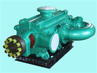
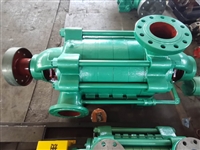
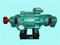
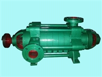
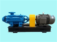
Overview of D-type series multi-stage centrifugal pump
The D-type series multi-stage centrifugal pump is a single suction multi-stage segmented centrifugal pump used for transporting clean water and liquids with physical and chemical properties similar to water. The head of this pump is H23 to 153.6 meters, and the flow rate is 12.6-39.6m3/h. The high temperature of the liquid shall not exceed 80 ℃
Scope of application of D-type series multi-stage centrifugal pump
Suitable for industrial and urban water supply and drainage, high-rise building pressurized water supply, garden sprinkler irrigation, fire pressurization, long-distance water supply, heating, bathroom and other cold and warm water circulation pressurization and equipment matching, especially suitable for small boiler water supply

Technical parameters of D-type series multi-stage centrifugal pump
Flow rate: 6.3-300m3/h;
Lift: 13-650m;
Power: 2.2-400KW;
Speed: 1450-2950r/min;
Caliber: 50-200;
Temperature range: ≤ 105 ℃;
Work pressure: ≤ 3.0Mpa.
Product Structure Description of D-type Series Multi stage Centrifugal Pump
The D-type series multi-stage centrifugal pump is a multi-stage segmented type, with the suction port located on the inlet section in a horizontal direction and the discharge port vertically upward on the water section. Its head can be adjusted according to the needs of use to increase or decrease the number of pump stages. Whether the water pump is well assembled or not has a significant impact on its performance, especially the outlet of each impeller and the inlet and outlet center of the guide vanes. Any slight deviation will reduce the flow rate and head of the water pump, resulting in poor efficiency. Therefore, attention must be paid during maintenance and assembly.
The main components of the D-type series multi-stage centrifugal pump include: inlet section, middle section, outlet section, impeller, guide vane baffle, outlet section guide vane, shaft, sealing ring, balance ring, shaft sleeve, tail cover, and bearing body. The inlet section, middle section, guide vane baffle, outlet guide wing, outlet section, and tail cover are all made of cast iron, forming the working chamber of the pump together. The impeller is made of cast iron and has blades inside. The liquid enters on one side along the axial direction. Due to the unequal pressure on the impeller before and after, there must be axial force, which is borne by the balance plate. The impeller is manufactured through static balance testing. The shaft is made of carbon steel and is equipped with an impeller in the middle. It is fixed to the shaft with keys, shaft sleeves, and shaft sleeve nuts. One end of the shaft is equipped with a coupling component, which is directly connected to the motor. The sealing ring is made of cast iron to prevent high-pressure water from leaking back into the inlet section of the water pump. It is fixed on the inlet and middle sections respectively and is a vulnerable part. After wear, it can be replaced with spare parts. The balance ring is made of cast iron and fixed on the outlet section. It forms a balance device together with the balance. The balance plate is made of wear-resistant cast iron and is installed on the shaft, located between the water outlet section and the tail cover, to balance axial forces. The shaft sleeve is made of cast iron and is located at the packing chamber. It is used to fix the impeller and protect the pump shaft. It is a vulnerable part and can be replaced with spare parts after wear. The bearing is a single row radial ball bearing lubricated with calcium based grease. The packing plays a sealing role, preventing air from entering and a large amount of liquid from leaking out. The packing seal consists of a packing chamber on the inlet section and tail cover, a packing gland, a packing ring, and packing, etc. A small amount of high-pressure water flows into the packing chamber to act as a water seal. The tightness of the filler must be appropriate, neither too tight nor too loose, based on the ability of the liquid to seep out drop by drop. If the packing is too tight, the shaft sleeve will absorb heat and consume power at the same time. The packing is too loose, which reduces the efficiency of the water pump due to liquid loss.
Product features of D-type series multi-stage centrifugal pump
1. The hydraulic model is advanced, efficient, and has a wide range of performance.
2. The pump runs smoothly with low noise.
3. The shaft seal adopts soft packing seal or mechanical seal, which is safe, reliable, structurally simple, and easy to maintain.
4. The shaft is a fully sealed structure, ensuring no contact with the medium, no corrosion, and a long service life.
Faults and troubleshooting of D-type series multi-stage centrifugal pump
Fault
reason
solution
1. The water pump does not absorb water The pointers of the pressure gauge and vacuum gauge jump violently
The water injected into the pump is not enough No matter if there is air leakage with the instrument
Inject water into the water pump again Tighten and block the leak.
2. The water pump does not absorb water The vacuum gauge indicates a high degree of vacuum.
The bottom valve is not open or has been blocked. The resistance of the suction pipe is too high. The water absorption height is too high
Correct or modify the condition of the bottom valve Or modify the suction pipe. Reduce the water absorption height.
3. The pressure gauge has pressure But the water pump still doesn't come out
The resistance of the outlet pipe is too high The rotation direction is incorrect, and the impeller is blocked The speed of the water pump is not enough
Inspect or shorten water pipes and inspect motors. Remove the water pipe joint and clean the impeller. Increase the speed of the water pump shaft
4. The flow rate is lower than the design requirements
The water pump is blocked Excessive wear on the sealing ring Insufficient rotation speed.
Clean the water pump and pipes Replace the sealing ring Increase the speed of the water pump shaft
5. The power consumption of the water pump is too high.
The packing gland is too tight The heating impeller of the grave material box is worn The water pump supply system has increased
Loosen the packing cap. Replace the impeller Increase the resistance of the outlet pipe to reduce flow.
6. The internal sound of the water pump is abnormal and the water pump does not fill water.
Too much traffic Excessive resistance inside the suction pipe. There is air at the water absorption point; Participate. The temperature of the liquid being sucked is too high.
Increase the resistance inside the outlet pipe to reduce flow. Inspect the suction pipe of the pump. Inspect the bottom valve Reduce water absorption height Block the leak Reduce the water absorption height.
7. Pump vibration
The pump shaft and the electromechanical system are not on the same centerline Or the pump shaft may be misaligned
Align the shaft centers of the water pump and motor,
8. The bearing is overheated.
No oil. The water pump and motor shaft are not on the same centerline.
Come on. Align the axis centerline and inspect or clean the bearing body.
D-type series multi-stage centrifugal pump for loading, unloading, starting, running, and stopping
(1) Connection sequence:
1) Tightly install the sealing rings on the inlet section and guide vane baffle respectively.
2) Install the guide wing on the middle section, and then install the guide wing baffle on all the middle sections.
3) The installed shaft sleeve A and suspected shaft are inserted through the water inlet section and pushed into the impeller. A layer of paper pad is placed on the middle section, and the middle section is installed. Then, the second impeller is pushed in, and the above steps are repeated to complete the installation of all impellers and the middle section.
4) Install the balance ring, balance sleeve, and outlet guide wing onto the water section separately.
5) Install the water outlet section on the middle section, and then tighten the water inlet section, middle section, and water outlet section together with tightening bolts.
6) Install the flat punch plate and shaft sleeve B (not included in the 50DB pump).
7) Install the paper pad onto the tail cover, install the tail cover onto the outlet section, and sequentially install the packing, packing ring, and packing cover into the packing chambers of the inlet section and tail cover.
8) Install the bearing bodies separately onto the inlet section and the tail cover, and tighten them with bolts.
9) Install the bearing positioning sleeve, ball bearing, and secure with nuts.
10) Add an appropriate amount of butter into the bearing body, and cover the bearing cover with a paper pad. Install the bearing cover onto the bearing body and tighten it with screws.
11) Install the coupling components, air release cock, and all square screw plugs.
Disassemble according to different steps
(2) Installation:
1. Preparation work before installation.
1) Check the water pump and motor.
2) Prepare tools and lifting machinery.
3) The foundation of the inspection machine.
2. Installation sequence:
1) The entire water pump has been transported to the site, and the electric motor has been installed with the base. It is not necessary to remove the water pump and motor when looking for a flat base.
2) Place the base on the foundation, place wedge-shaped shims near the anchor screws, and raise the base by about 20 degrees? 40mm, ready to level and fill with water grout.
3) Use a spirit level to check the levelness of the base, level it, tighten the foot nuts, and fill the base with cement slurry.
4) Through 3? After 4 days of cement solidification, check the water level again.
5) Clean the dirt on the support plane of the base, the water pump foot, and the motor foot plane; , and place the water pump and motor on the base.
6) Adjust the level of the pump shaft, tighten the nut appropriately after leveling to prevent movement. After the adjustment is completed, install the motor. Place an iron plate at the non level position, and leave a certain gap between the pump and the coupling.
7) Place a ruler on the coupling and check if the axis of the water pump coincides with the axis of the motor. If not, place a thin sheet under the feet of the motor or pump to make the outer circles of the two couplings level with the ruler. Then take out several thin iron sheets from the pad and replace them with a whole iron plate that has been planed, and recheck the installation. In order to check the installation accuracy, use a feeler gauge at several opposite positions to measure the gap between the two coupling planes. The difference between the large and small gaps on the coupling plane should not exceed 0.3 millimeters, and the difference between the center lines of both ends should not exceed 0.1 millimeters.
(3) Start and Stop:
1) Apply all the oil that has been sprayed on the shaft and other oiled parts.
2) Clean the bearings and oil chamber with gasoline, and wipe them clean with cotton yarn.
3) Add calcium based spring oil into the bearing body.
4) The experiment was successful Check if the motor direction is correct Strictly prevent the water pump from turning and loosening the nut Then start the motor.
5) Inject water into the pump or empty the pump to draw water.
6) Close the valve and pressure gauge plug on the discharge pipe.
7) After the above process is completed Start the motor Open the pressure gauge plug
8) When the water pump is running at normal speed, the pressure gauge displays the appropriate pressure Then open the vacuum gauge and gradually open the gate valve on the drainage pipeline until the required pressure is reached.
9) When stopping the water pump Slowly close the gate valve on the drainage pipeline Close the vacuum gauge plug And stop the motor Then close the pressure gauge plug.
10) When the water pump is stopped for a long time The water pump should be disassembled Wipe off the water from the pump components And apply rust proof oil on the sliding surface for proper storage.
(4) Operation
1) Pay attention to the temperature of the water pump bearings It shall not exceed the external temperature of 351, and its maximum temperature shall not exceed 751^
2) The normal degree of water leakage in the grave material room Not exceeding 15 milliliters per minute The degree of compression of the packing gland should be adjusted at any time.
3) Regularly inspect the shaft and pay attention to the temperature rise of the motor bearings.
4) During operation If there is a sound or abnormal sound The vehicle should be stopped immediately to investigate the cause
Ordering Instructions
1、 ① Product name and model of D-type multi-stage centrifugal pump ② Diameter of D-type multi-stage centrifugal pump ③ Head of D-type multi-stage centrifugal pump (m) ④ Flow rate of D-type multi-stage centrifugal pump ⑤ Motor power of D-type multi-stage centrifugal pump (KW) ⑥ Rotational speed of D-type multi-stage centrifugal pump (r/min) ⑦ Voltage of D-type multi-stage centrifugal pump j [V] ⑧ Suction stroke of D-type multi-stage centrifugal pump (m) ⑨ Whether the D-type multi-stage centrifugal pump comes with accessories for us to correctly select for you.
2、 If the design unit has already selected our company's D-type multi-stage centrifugal pump product model, please order directly from the sales department of Yangtze River Pump Industry Company according to the D-type multi-stage centrifugal pump model.
3、 When the usage situation is very important or the environment is complex, please provide design drawings and detailed parameters as much as possible, and our technical experts from Hunan Zhongda Pump Industry will review and control them for you.
AfterSalesService :
Key words:- Horizontal Centrifugal Pump


