


OPPC-24b1-120/25 OPPC fiber optic cable supplier is selling well in stock
Category:
Electrical Engineering/Wire and cable/Fiber optic cable
Model:
OPPC-24B1-120/25
Brand:
Dazheng Electric Wire Co., Ltd
Retail Price
9.60USD
重量
kg
- Product Description
-
Description :
Construction methods and precautions for OPPC power optical cables
 item
item 1. Construction preparation
1.1 Determine the construction plan, and the design unit shall disclose the construction design drawings to the construction unit. The construction unit shall prepare an OPPC optical cable installation construction plan based on the project overview, line routing, reserved connection positions for optical cables, etc., and review the relevant information. Based on OPPC design technical specifications, factory reports, and other materials, understand OPPC mechanical performance, transmission characteristics, connection losses, and other indicators to prepare for on-site product testing and final acceptance.
1.2 Remarks on Construction Tools and Instruments: Auxiliary facilities such as transportation vehicles, cranes, climbing boards, safety helmets, safety belts, grounding wires, electrical testers, ropes, red and white flags, bamboo, protective nets, safety warning signs, etc. must be fully prepared before installation.
one
After the on-site testing and acceptance of OPPC and fittings accessories materials arrive at the construction material warehouse, relevant parties such as the owner, supervisor, construction party, and factory representative should be organized to jointly conduct on-site unpacking and acceptance of the received materials. Compare the contract with the construction drawings issued by the design unit, conduct performance tests on the received optical cables, count the hardware accessories, verify the model, confirm the quantity, etc. Check if the received products have been damaged during transportation. After passing the on-site inspection and acceptance, all parties involved shall complete the signing and handover procedures. 1)
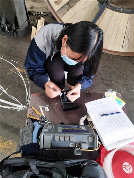
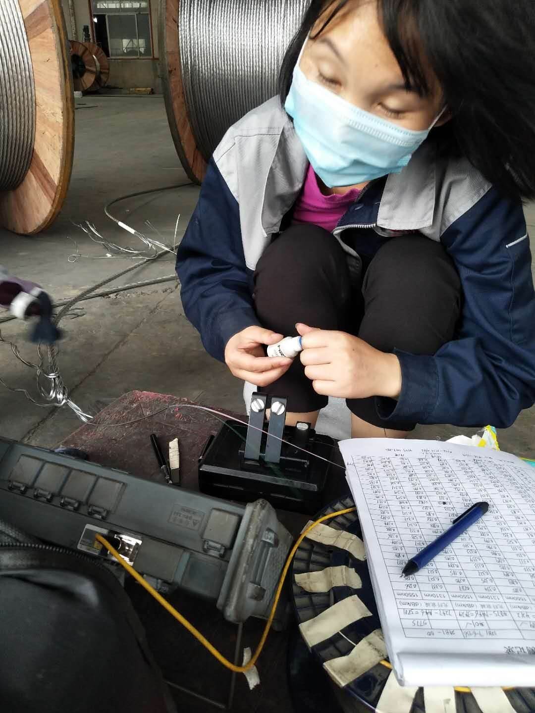
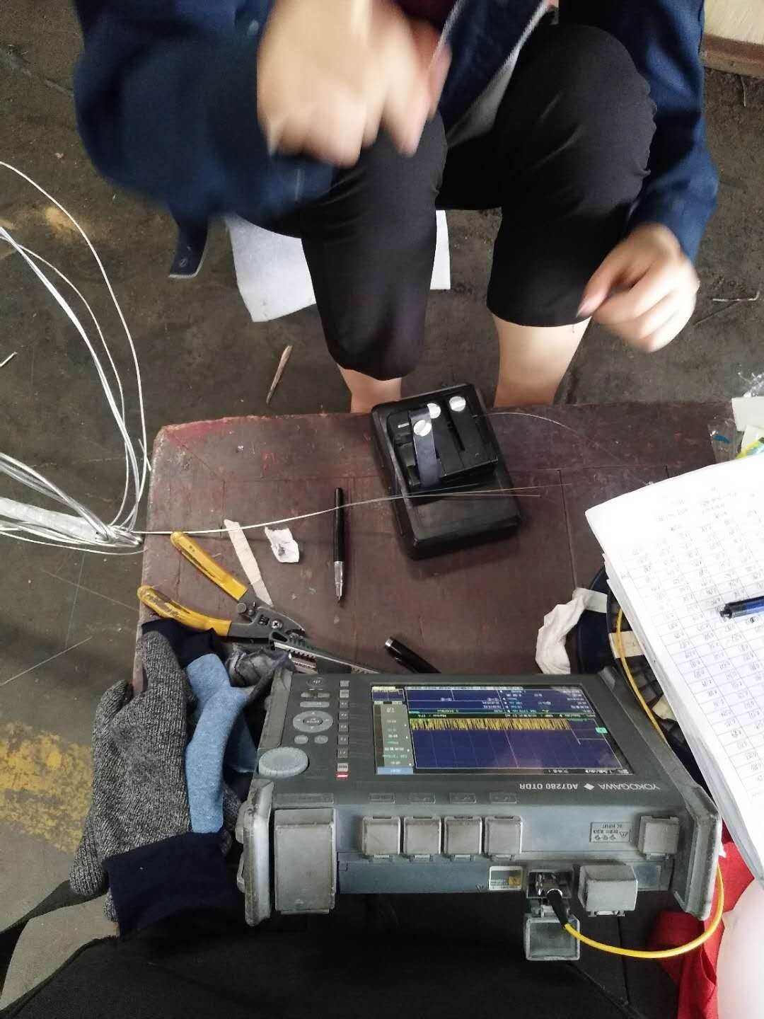
The OPPC opening test uses a portable optical time domain reflectometer (OTDR) to perform fiber core continuity testing, fiber core length testing, and fiber attenuation performance testing (usually on-site testing at 1550nm wavelength). Simultaneously record and save the test data (fiber backscatter curve). The optical cable must be tested and qualified before installation. 2) The material station for each construction section should count, classify, and install the metal fittings according to the quantity specified in the design drawings and technical agreements. If any problems are found, they should be promptly contacted for replacement. The material custodian must distribute materials according to the requirements of the design drawings.
1.4 Construction technology training disclosure: Strictly implement the technical management regulations of the power industry, power safety work procedures, and on-site maintenance regulations, and provide effective training for construction operators and testers. Technical briefing shall be conducted before construction, with technical personnel or on-site construction supervisors explaining the structural performance, quality standards, construction steps, requirements for construction tools, construction precautions, and methods of using hardware accessories of OPPC. If necessary, operation demonstrations and trial assembly (such as tension clamps, suspension clamps, etc.) shall be carried out. Discuss construction plans under special conditions.
2. Construction Exhibition 2.1 Installation Method OPPC The commonly used installation and wiring method for OPPC is recommended to be tension laying method. Tension laying method uses tension equipment to subject OPPC to a certain constant tension throughout the entire laying process, ensuring sufficient clearance with obstacles and other objects, avoiding friction, and not damaging OPPC. At the same time, it can reduce compensation for young crops, alleviate physical labor, and improve construction progress, as shown in the following figure. 2.2 Control of the unfolding process: 1) Select a traction rope that matches the cable diameter. Before construction, the traction rope should be carefully inspected, and rusty and broken traction ropes should not be used. At the same time, the traction net sleeve should be carefully checked for damage and broken strands, and the torque reducer should be rotated flexibly. 2) The applied tension is generally controlled within 10% RTS, and any tension applied to the optical cable during construction should not exceed 20% RTS. The optical cable cannot land during the deployment process, ensuring a safe distance of 3-5m between the cable and the crossing object. Each signal personnel should observe the deployment of the optical cable at any time, promptly notify and adjust the tension, and avoid the optical cable from colliding with the already installed wires, crossing frames or other obstacles, causing wear or bending. 3) The initial laying speed is 5m/min, and after the optical cable passes through the base tower, it can be uniformly accelerated to around 30m/min. The laying speed should not exceed 40m/min. When towing, try to move forward at a constant speed. Sudden acceleration or deceleration is strictly prohibited, and shaking during laying is strictly prohibited.
4) During construction, the operator of the tension machine should always pay attention to the tension control situation. During the traction process, if the traction force suddenly increases significantly or the metal fittings of the hanging pay off pulley are tilted too much, it should be considered abnormal. The machine should be stopped in a timely manner, and the cause should be identified and the fault eliminated before traction can be resumed.
5) To prevent fiber optic cables from jumping at corners or turns, pulleys at corners or turns need to be pre biased at appropriate angles. When laying out the line, there must be a dedicated person to supervise the top of each corner tower and the crossing point, in order to promptly report and handle any wire clamping or other situations. The fiber optic cable traction end should pass through the pulley under the supervision of the construction personnel. 6) After the installation of the optical cable is completed, the reserved length of the optical cable on the splicing tower should meet the requirements of splicing, usually 10 meters can be reserved. 7) During the exhibition process, the signal should be kept unobstructed.
2.3 Tightening and Hanging of Cables 1) The tension of the tensioning cable should not exceed 20% RTS to ensure that the performance of the optical fibers in the cable is not affected, otherwise it may cause potential damage to the optical fibers in the cable. 2) When tightening the cable, tighten it in one direction, especially when there are multiple tension sections in the line. Do not tighten the cable from both ends to the middle, so as to prevent the torque on the cable from being released and causing a "birdcage" or loose strand in the drainage section. 3) When using a cable tightening tool to clamp the optical cable, the tool should be clamped at the end of the cable to ensure that the tool does not affect the normal use of the cable in situations where it may damage the cable. When directly tightening OPPC or adjusting tension sag, it is recommended to use pre twisted wire as a cable tightening tool. The tension resistant fittings of the cable can be used as a tightening tool once and must be used as installation materials for the second use. It is strictly prohibited to use wire guides (ground) to clamp OPPC. 4) The reserved length for small sag of jumper wires in straight through tension towers is generally 2-3 meters, which can be adjusted according to the angle or direction of the tower's rotation. 3. After installing the OPPC optical cable in a tension resistant section, in order to prevent the optical cable from being worn on the surface inside the pulley and causing excessive fatigue and damage to the optical fiber due to vibration, the metal fittings should be installed within 48 hours. Hardware accessories should be installed strictly in accordance with the optical cable construction drawings provided by the design unit and the user manual provided by the hardware accessory manufacturer.
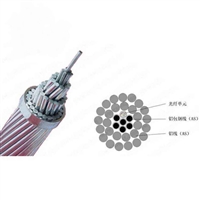
3.1 Installation of Suspension Hardware Pre twisted Wire Suspension Clamp is used to suspend optical cables on towers and provide support, similar to the suspension clamps used in typical transmission and distribution lines. Each straight tower is equipped with one set. The standard hanging pre twisted wire clamp consists of inner twisted wire, outer twisted wire, cast aluminum shell, rubber clamp block, bowl head hanging ring, insulator, ball head hanging ring and other structures.
3.2 Installation of tension fittings: The tension clamp is a key fitting for setting up OPPC. It not only needs to fasten the optical cable to the tower, withstand high tension, but also has a strong grip on the optical cable, and cannot exceed the lateral compressive strength of the optical cable. The standard pre twisted tension clamp consists of internal twisted wire, external twisted wire, extension ring, bowl head hanging plate, insulator string, ball head hanging ring, UL type hanging plate and other structures.
3.3 Installation of Anti vibration Hammer Anti vibration hammer is mainly used to eliminate or reduce the vibration caused by various factors during the operation of OPPC optical cables, thereby protecting the optical cables and fittings and extending the service life of OPPC. The installation quantity and location of vibration dampers should strictly follow the design specifications or drawings provided by the hardware manufacturer. 4. Fiber optic splicing and full process testing 4.1 OPPC fiber optic splicing OPPC splicing is an important part of the entire project. OPPC splicing involves fiber optic splicing and optoelectronic separation technology, with strict requirements for splicing technology and high-voltage insulation. It is generally operated by fiber optic splicing personnel. OPPC splicing is generally carried out on tension towers, and OPPC splice boxes are divided into intermediate and terminal types.
4.1.1 Intermediate joint box (1) Select intermediate joint boxes with different fixing methods according to the form of the tension tower: pillar type intermediate joint box (using fixed seat insulators) and suspension type intermediate joint box (using suspension insulators).
OPPC pillar type intermediate joint box
The OPPC suspended intermediate joint box (2) selects the installation position of the joint box on the splicing tower and installs a fixed platform (using a pillar type intermediate joint box), which can also serve as an operating platform for fiber optic splicing. The platform is generally installed at a distance of about 3.5m below the cross arm of the tower.
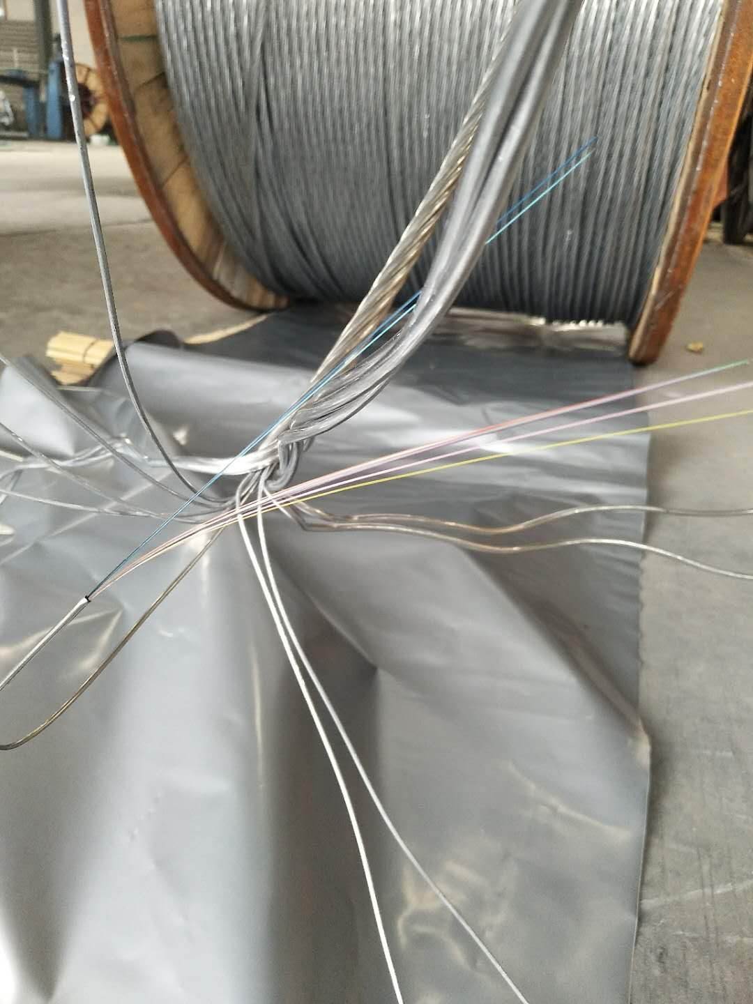
(3) Fix the intermediate junction box on the platform, then determine the distance between the fiber optic cable from the hardware hanging point to the junction box, and reserve enough fiber optic length for splicing inside the box (generally controlled at around 1.5m). After that, cut off the excess fiber optic cable. (4) Peel off the OPPC optical cable and separate the steel tube optical unit. Use a steel tube cutter to cut and strip the stainless steel tube at a distance of about 30mm from the OPPC inner cutting surface. Thread inner lining tubes and fiber optic protection conduits inside and outside the steel tube, and pay attention to protecting the fiber optic cable. (5) Fix the OPPC optical cable on the junction box, fix the fiber protection conduit on the fiber optic plate, and perform fiber fusion splicing.
Welding on OPPC tower
(6) Encapsulate the junction box and use a power jumper with a parallel groove clamp to cross the OPPC at both ends of the junction box, ensuring the continuity of the wires. As shown in the figure below. Installation diagram of OPPC suspended intermediate joint box
Installation diagram of OPPC pillar type intermediate joint box 4.1.2 Terminal joint box Terminal joint box is generally fixed, as shown in the figure below. Its installation and connection are divided into the installation of the lower box body and the connection of the upper joint box.
Installation of OPPC terminal junction box (1) lower box body: Install the platform and lower box body of the terminal junction box at a suitable position on the terminal junction tower, strip off the outer sheath of the introduced optical cable, pass the fiber sheath through the hollow insulator of the junction box to the upper box body for fiber splicing, and fix the introduced optical cable. The recommended length for fiber optic protective sleeves is generally around 2 meters.
(2) Installation of the upper junction box: The installation of the upper junction box can be carried out according to the installation of the middle junction box. (3) Fix and package the terminal box, and connect the OPPC at the upper box to the phase terminal with a jumper wire clamp to ensure the continuity of the wires, as shown in the following figure.
Installation diagram of OPPC terminal junction box
4.2 Full process testing: After the completion of the optical cable construction, a bidirectional full process testing should be carried out, including the testing of unidirectional fiber fusion loss and the calculation of bidirectional average loss and average attenuation. The test results should meet the contract requirements. (1) The unidirectional loss of the optical cable is tested using an optical time domain reflectometer. The backscatter signal curve and event table should be provided at the same time, and the average bidirectional loss should be calculated based on the test results. (2) Using the optical power method to retest the total loss of the optical cable throughout the entire process and verify the sorting of the fiber cores. 2. Check the distribution diagram of the optical cable line from the ODF at the A end to the ODF at the B end. The diagram should indicate the length of the guiding optical cable, the installation length of each optical cable, the location of the splice box, and the hanging parameters.
3. Check the fiber distribution diagram of the fusion point of the optical cable line from the ODF at the A end to the ODF at the B end. 5. Quality Control Points 5.1 Transportation and Storage Control Points: Check whether optical cables, fittings, and accessories are worn during transportation, and whether they are damp or corroded during storage. 5.2 Key points for cable laying and tightening control: The bending radius of the optical cable during the laying process must be effectively ensured, and efforts should be made to avoid the occurrence of golden hooks. Prevent excessive tension, wear, bending, and twisting of optical cables.
5.3 Attachment installation control points: To prevent excessive tightening torque of various bolts on the optical cable under stress, and to prevent wear, bending, and unreasonable compression of the optical cable. 6. Construction precautions: 1. Before construction, the frequency and sensitivity of the walkie talkie should be verified; During the cable laying process, practical situations and past experience should be considered, and unified dispatch and command should be followed. 2. During installation, OPPC and all metal instruments must be reliably grounded to avoid injury to personnel and equipment caused by capacitive and inductive coupling.
3. After the fiber optic cable end is pulled out from the cable reel, it cannot be directly wound onto the tension machine. Instead, a soft rope should be used to wrap it around the tension machine before pulling it through to avoid artificially increasing the torque of the fiber optic cable. 4. The installation of OPPC cannot be carried out in harsh weather conditions such as strong winds and thunderstorms; It is necessary to implement the "Electricity Safety Work Regulations", fill out work tickets, implement organizational measures for high-voltage overhead line safety work, and comply with relevant work regulations of the power system. 5. Although the structure of OPPC optical cables is sturdy and durable, it is still important to avoid unnecessary damage to the cables due to incorrect operation during installation. During the OPPC laying process, there should be no sudden vibration, pulling, or wire jumping. 6. When working on streets and highways, OPPC should be placed in the same direction as the traffic flow, and a dedicated person should be assigned to direct the traffic. Warning and traffic guidance signs should be used to delineate the work area, and if necessary, assistance from public security traffic police can be sought to divert traffic.
AfterSalesService :
Key words:- OPPC fiber optic cable supplier
More Products


