


Zhoushan inclinometer pipe inclinometer pipe burying technology inclinometer instrument use
Category:
building materials/Construction and building materials pipes/Composite tube
Model:
70mm
Brand:
Cangzhou Shuntian
model:
70mm
tensile strength:
370MPa~480MPa
Processing Service:
deep processing
execution standard:
National Standard
quality grade:
A-level
Processing & Customization:
yes
Is it imported:
No
nominal outer diameter:
seventy
wall thickness:
five
Is it a cross-border source of goods:
No
Retail Price
13.00USD
重量
kg
- Product Description
-
model 70mm
tensile strength 370MPa~480MPa
Processing Service deep processing
execution standard National Standard
quality grade A-level
Processing & Customization yes
Is it imported No
nominal outer diameter seventy
wall thickness five
Is it a cross-border source of goods No
Description :
Zhoushan inclinometer pipe inclinometer pipe burying technology inclinometer instrument use measuring point burying and technical requirements
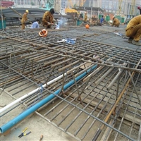
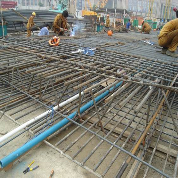
1) Burial method
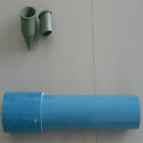
The inclinometer pipe is tied and buried. The inclinometer tube is directly tied and fixed to the reinforcement cage of the retaining pile. After the reinforcement cage is inserted into the groove (hole), concrete is poured.
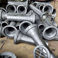
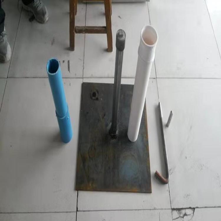
On site processing drawing of inclinometer tube
2) Technical requirements for burial
Due to the construction conditions on site, the installation and protection of inclinometers are relatively difficult, and the finished product rate is low. Therefore, the installation and installation of inclinometers for supporting structures should follow the following principles:
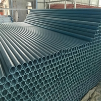
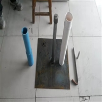
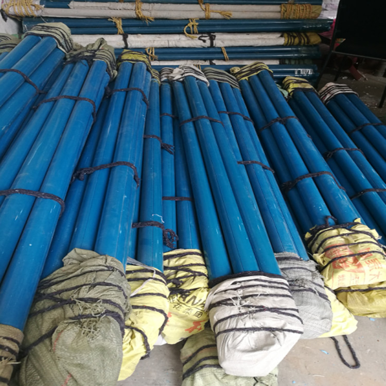
① The bottom of the pipe should be level with or slightly lower than the bottom of the steel cage, and the top should reach the ground (or the top of the guide wall). The top of the inclinometer tube should be protected as much as possible. For example, during on-site installation, we can use steel pipes as protective covers to cover the upper part of the inclinometer tube. As the inclinometer tube is made of PVC material, it is easy to break. In addition, on-site construction often uses fragmentation cannons to clean the heads of retaining piles, which can easily damage the inclinometer tube. When using steel pipes for protection, cut off the protective steel pipes after cleaning the pile head. Fill the pores between the steel pipe and the inclinometer pipe with pea gravel concrete or cement mortar to stabilize the inclinometer pipe. This can protect the inclinometer tube and improve the yield of inclinometer tube installation.
② The reinforcement cage of the inclinometer pipe and the supporting structure should be tied and buried, with a binding spacing of no more than 1.5m.
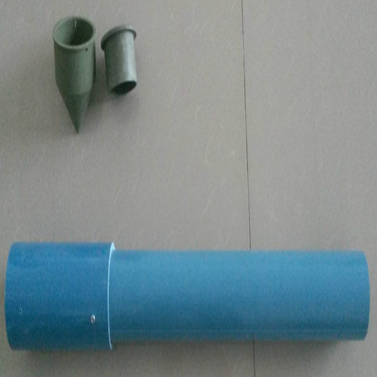
③ The inner lining of the upper and lower pipes of the inclinometer tube is well connected without gaps, and the joint is firmly fixed and sealed.
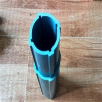
④ When tying the pipe, the direction should be adjusted so that a pair of measuring slots inside the pipe are perpendicular to the measuring surface (i.e. parallel to the displacement direction).
⑤ Seal the bottom and top, keeping the inclinometer tube clean, unobstructed, and straight.
⑥ Make clear markings and reliable protective measures (Figure 5-20).


(3) Monitoring methods and data collection
1) The monitoring instrument adopts CX-03E inclinometer and matching PVC inclinometer tube. The instrument diagram is shown in the following figure
inclinometer
2) Observation method:
① Use a simulated probe to inspect the inclined pipe guide groove.
② Place the inclinometer reader in working condition, insert the probe guide wheel into the guide groove of the inclinometer tube, slowly lower it to the bottom of the tube, and then read the data every 0.5m along the entire length of the guide groove from bottom to top, recording the depth of the measuring point and the reading. After the reading is completed, rotate the measuring head 180 ° and insert it into the same pair of guide slots. Measure again using the above method, with the same depth at the same depth.
③ The values of the positive and negative readings at each depth should be the same, and any abnormal readings should be promptly retested.
3) Observation precautions
① Before observation, a detailed inspection of the inclinometer hole should be carried out. During our monitoring and construction, we often find that the simulated measuring head is stuck in the inclinometer tube. So, as a pre measurement task, it is essential to be meticulous. We can take a sample of the proposed diameter 28 at the construction site? A 32 meter steel bar is tied to the steel bar with a rope, and then placed inside the inclined bamboo and pulled up and down. Simulate the same motion trajectory as the inclinometer probe, so cycle up and down several times. Then use the side probe for measurement, which basically ensures that the analog probe is not stuck in the inclinometer tube, thereby reducing unnecessary losses.
① Initial value determination: The inclinometer tube should be installed 5 days before the test, and at 3? Within 5 days, use a inclinometer to perform 3 repeated measurements on the same inclinometer tube. Once it is confirmed to be in a stable state, use the arithmetic mean of the 3 measurements as the reference plane for calculating lateral displacement.
② Observation requirements: The inclinometer probe should be placed at the bottom of the inclinometer tube and wait for 5 minutes to adapt to the water temperature inside the tube. During observation, attention should be paid to the sealing of the instrument probe and cable to prevent water from entering the data transmission part of the probe. During inclinometer observation, the mark must be stuck in the same position every 0.5m, and the voltage value must be stable before reading to ensure the accuracy of the reading.
(4) Data processing and analysis
Schematic diagram of inclinometer
Firstly, it is necessary to set a reference point. The reference point for observing the deformation of the retaining pile body is generally located at the bottom of the inclinometer tube. When the measured pile body undergoes deformation, the axis of the inclinometer tube deflects. By using an inclinometer to determine the inclination angle of each section of the inclinometer tube axis, the horizontal displacement of the pile body can be calculated.
AfterSalesService :
Key words:- Zhoushan inclinometer pipe
More Products