


Yiyang Observation Standard Observation Nail Distributor Cangzhou Shuntian Stainless Steel Observation Standard Galvanized Observation Standard
Category:
metallurgy/Stainless steel material/Stainless steel bars
Model:
Brand:
Cangzhou Shuntian
grade:
Observation standard
cross-sectional shape:
round bar
surface treatment:
glossy surface
Processing Technology:
Forging
tensile strength:
370MPa~480MPa
Processing Service:
deep processing
execution standard:
National Standard
quality grade:
A-level
Processing & Customization:
yes
Is it imported:
No
weight:
one
Scope of application:
rail transit
delivery service:
Can be delivered to the factory
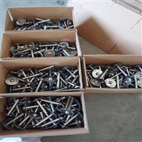
Type of goods sales:
spot
Item Number:
twenty thousand one hundred and twenty
warehouse address:
Cangzhou, Hebei
warehouse phone:
fifteen billion one hundred and three million three hundred and seventy-two thousand six hundred and sixty-seven
manufacturer:
Cangzhou Shuntian Steel Pipe Co., Ltd
Retail Price
5.00USD
重量
kg
- Product Description
-
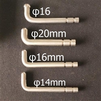
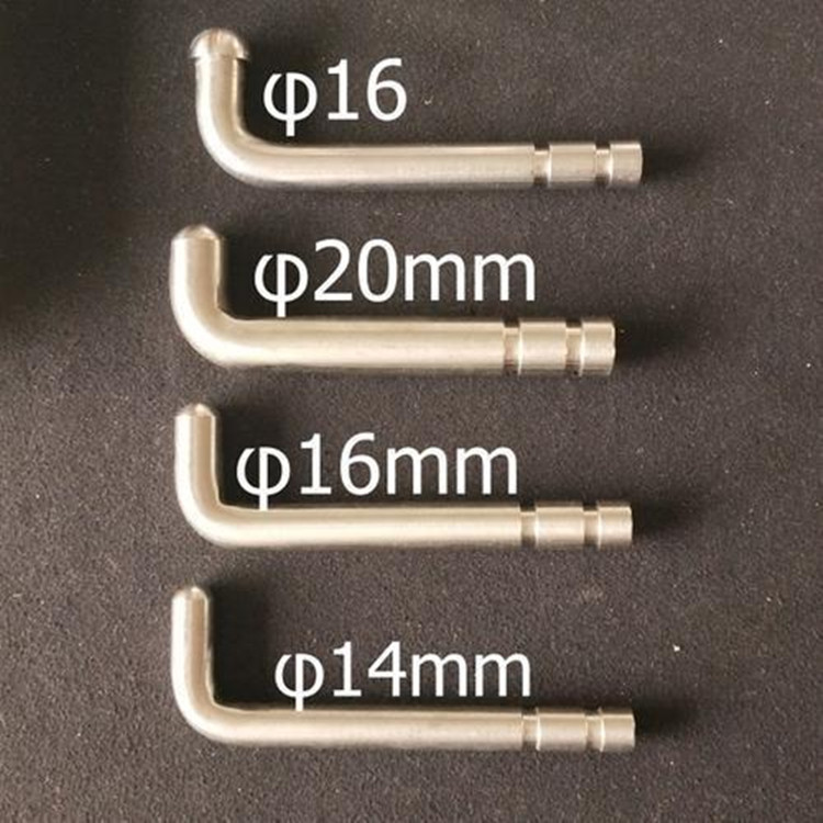
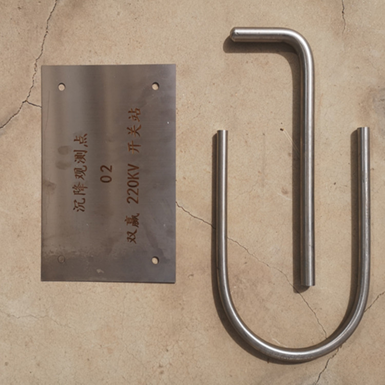
grade Observation standard
cross-sectional shape round bar
surface treatment glossy surface
Processing Technology Forging
tensile strength 370MPa~480MPa
Processing Service deep processing
execution standard National Standard
quality grade A-level
Processing & Customization yes
Is it imported No
weight one
Scope of application rail transit
delivery service Can be delivered to the factory
Type of goods sales spot
Item Number twenty thousand one hundred and twenty
warehouse address Cangzhou, Hebei
warehouse phone fifteen billion one hundred and three million three hundred and seventy-two thousand six hundred and sixty-seven
manufacturer Cangzhou Shuntian Steel Pipe Co., Ltd
Description :
The main bridge of Jinan Yellow River Phoenix Bridge adopts the design concept of "Zhong Lingyu Xiu", and the approach bridge adopts the design concept of "Chang Hong Wo Bo". The design concept of the entire bridge is in line with the artistic conception of "Magpie Hua Qiu Se Tu", fully reflecting the characteristics of Jinan and showcasing its humanistic culture.
Design features
structural characteristics
overall
The main bridge is a three tower six span spatial cable surface composite beam self anchored suspension bridge, using a semi floating system, with tower piers consolidated and tower beam separated. Vertical supports are provided between the stiffening beam and the bridge tower and pier, and longitudinal liquid viscous damping is provided between the stiffening beam and the bridge tower. Horizontal steel dampers are installed between the stiffening beam, bridge tower, and side piers.
main beam
① The stiffening beam is a composite beam made of equal height steel and reinforced concrete. The steel beams are closed steel box girders, and fiber reinforced concrete bridge decks are installed in the motor vehicle lane and cable suspension system areas. Suspension cables and stiffening beam anchoring structures are installed on the top of the mid span and side span beams, and the steel box girders and concrete bridge decks are connected by welding nails.

② The steel beam adopts a closed steel box girder with external cantilever arms. The standard cross-section of the side and mid span adopts a single box three room cross-section, and the top and bottom plates of the tower column are reinforced with holes to allow the bridge tower to pass through; The transverse partitions of the steel box girder are all truss type hollow partitions, and the web members of the truss are made of double angle steel. Two transverse stiffeners are set in the middle of the two transverse partitions, and a pair of full height vertical stiffeners are set in the web plate between every two transverse partitions. A local stiffener is set between the stiffeners and the transverse partition.
③ The top and bottom plates of the box girder are reinforced with U-ribs except for the plate ribs near the web plate; The web plates are reinforced with plate ribs. The steel beams are mainly made of 345qE steel and Q420qE steel, the rigid suspension rod ear plates are made of Q500qE steel, and the main cable anchoring structure is made of ZG300-500H steel.
④ Set up C60 fiber reinforced concrete bridge decks within the scope of the motor vehicle lane and cable suspension area; Welding nail connectors are installed between the steel beam top plate and the concrete slab to connect them as a whole. Bridge deck steel bars are arranged vertically in double layers and horizontally in single layers.
bridge tower
① Each bridge tower consists of two tower columns, two cow legs, a lower crossbeam, and an upper crossbeam. The cow leg is located on the outer side of the tower column, below the stiffening beam, and a vertical support for the stiffening beam is set on the cow leg; The lower crossbeam is located below the stiffening beam and is equipped with transverse and longitudinal dampers for the stiffening beam; The upper crossbeam is located below the saddle.
② The three bridge towers of the bridge are all of mixed structure, with steel structure above the flood level and steel mixed composite structure below. The steel structure material is Q420qE steel, and the concrete is C60 concrete.
③ The tower column adopts a pentagonal cross-section, and except for the decorative section at the top of the tower, which is a single box single chamber cross-section, the rest are single box three chamber cross-sections.
cable
① The cable hoisting system includes several parts such as the main cable, sling, cable clamp, main cable saddle, and loose cable sleeve.
② The main cable is arranged as a spatial double cable surface on the cross section, and each main cable is composed of multiple parallel strands, each containing galvanized aluminum alloy high-strength steel wire.
③ Slings are divided into flexible slings, rigid slings, and central buckles; The upper end of the flexible sling is connected to the cable clamp by a pin connection, and the lower end is connected to the stiffening beam by an anchor plate. Each sling contains multiple high-strength galvanized aluminum alloy steel wires; The upper and lower ends of the rigid sling are connected by pin connections, using an alloy structure and adjusting the length through a connecting sleeve. Three pairs of rigid central buckles are installed at the mid span position of the main cable. The central buckle body is a welded I-shaped section, with the upper end connected to the flange plate on the cable clamp through high-strength bolts, and the lower end bolted to the top plate of the stiffening beam through high-strength bolts.
④ There are three main types of cable clamps for the entire bridge, including suspension cable clamps that connect the main cable to the suspension cable, closed cable clamps at the entrance of the loose cable sleeve, and cone-shaped closed cable clamps with cable sleeves installed at the outlet of the main cable saddle. The cable clamp adopts an upper and lower mating structure, with the upper and lower halves of the cable clamp connected by screws and clamped onto the main cable. The joint is filled with rubber waterproof strips for waterproofing, and a waterproof nut is installed at the end of the cable clamp screw. The material of the cable clamp is ZG20Mn.
⑤ The main cable saddle adopts a casting welding combination form, and the material of the cable saddle head is ZG300-500H. The reinforcing ribs and bottom plate are made of Q345qE steel.
other
The bridge tower foundation adopts a rectangular pedestal, which is a drilled pile foundation. The main bridge piers and auxiliary piers are divided into
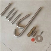
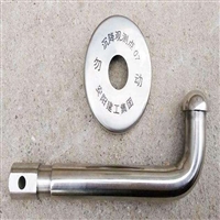
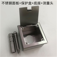
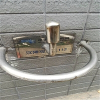
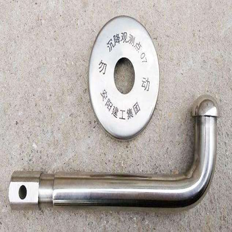
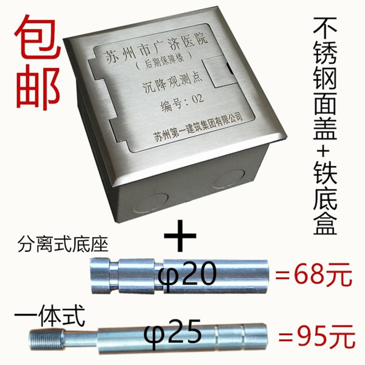
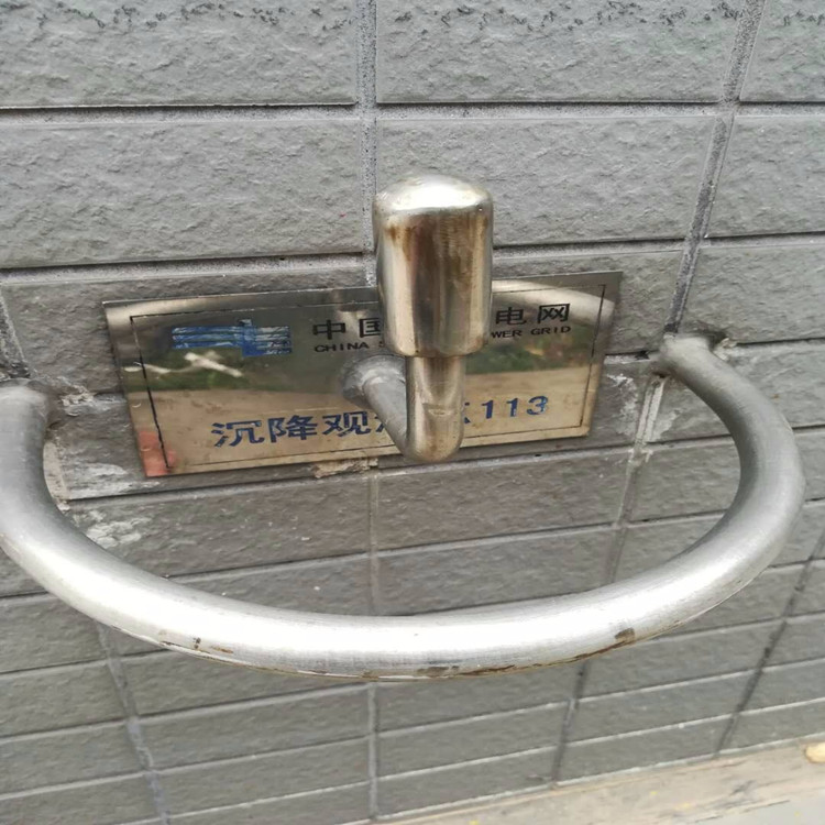
Observation point burial location and requirements
When setting up observation points for construction, they must be closely integrated with the structural parts of the building, without any looseness, and ensure stability and reliability throughout the entire observation period. If necessary, protective measures can also be added, and the observation points of industrial facilities need to consider factors that may cause disturbance or damage during equipment installation and construction. Civil high-rise building observation points should anticipate the impact of building materials falling from high altitude, such as damage or accumulation, on settlement observation points. The location of observation points should not be too high or too low, and should be set according to the natural floor of the construction site and the height difference between positive and negative zero elevations. If necessary, consult the construction unit for the elevation of backfill soil or building water before making a decision. If the natural ground level of outdoor construction is lower than the building by ± 0.00 and the height difference is more than 2000 mm, factors such as backfill soil that may affect later observation can be temporarily ignored. Before backfilling the project, secondary points can be set up to measure the elevation of the observation points and continue to observe at new points. Observation points belonging to industrial facilities still need to be communicated with the commissioning party to prevent intrusion into the observation points after equipment installation. When the observation point is buried in a concrete building, it should be fixed with planting adhesive. For steel structure buildings, welding should be used, and it is not recommended to use other methods as substitutes. The distance between the observation point and the structural column surface should be 40-50 mm to facilitate the placement of a level ruler.
AfterSalesService :
Key words:- Yiyang Observation Standard
More Products


