


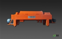

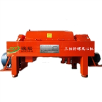
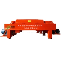
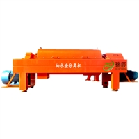
Kitchen leachate oil-water residue separator Kitchen leachate three-phase separator Leachate solid-liquid separator
Category:
chemical industry/Filtration, separation, and screening equipment/Centrifuge
Model:
WLS355
Brand:
Ruichen Environmental Protection
Retail Price
36,500.00USD
重量
kg
- Product Description
-
Description :
Kitchen leachate oil-water residue separator Kitchen leachate three-phase separator Leachate solid-liquid separator
The full name of this type of machine is the horizontal screw three-phase separator, which is a spiral discharge settling separator. The solid phase is pushed to the slag discharge port at the small end of the drum through the blades on the spiral pusher, and the liquid phase oil water overflows through the overflow holes at the large end of the drum. Continuously cycling in this way to achieve the goal of continuous three-phase separation of oil, water, and slag.
Working principle diagram of kitchen leachate oil-water residue separator:

Overview of the components of the kitchen leachate oil-water residue separator:
1. Drum drum
It is a cylindrical cone cylindrical rotor composed of a cone and a cylinder, designed to achieve better separation performance. When the drum rotates at high speed, it drives the slurry to rotate together. Under the action of centrifugal force, heavier solid particles will be separated from the liquid. The cylindrical part of the drum is designed to facilitate the clarification of the filtrate (centrifugal separation), while the conical part is beneficial for the dehydration of solid materials.
The working principle of the rotary drum of the horizontal spiral centrifuge
2. Spiral feeder
The spiral unloader accelerates the feeding of slurry and pushes the material deposited on the inner wall of the drum to the solid discharge end of the centrifuge. The two bearings supporting the spiral unloader are pressed into the two drum covers, and the bearings are separated from the processed material by the skeleton oil seal assembly assembled on the spiral core shaft. The spiral unloader is composed of a spiral core shaft, spiral blades, and two connecting plates that support the rotation of the spiral unloader. The spiral core shaft has a feeding chamber and several feeding holes. The feeding end journal is a hollow structure, and the feeding tube leads to the feeding chamber through the hollow journal. The differential end journal is a spline structure and is connected to the differential output spline
3. Bearing
The main bearings are all rolling bearings that support the entire rotor assembly. These bearings are assembled into bearing seat components, which are positioned by centering pins during installation and then fastened to the centrifuge base
The bearing seat components are made of cast iron material, and the feed end bearing is a fixed radial ball bearing. The drum is limited in axial movement by it, and the differential end bearing is a detachable roller bearing, which allows axial movement due to thermal expansion or contraction of the centrifuge.
4. Differential mechanism
The differential drives the spiral unloader and rotates it at a constant speed relative to the outer drum. The reduction ratio of the differential and the input shaft speed of the outer drum and differential determine the speed difference between the outer drum and the spiral unloader; Except for replacing lubricants, maintenance and repair of the differential can only be carried out by personnel trained by our factory. The transmission ratio of the gearbox has been selected, and the spiral unloader has obtained a speed that can meet the requirements of solid discharge volume and separation efficiency.
5. Cover shell
The casing consists of an upper casing and a lower casing; There is a sealing gasket on the mating surface of the upper and lower covers to prevent leakage of the machine body. The sealing gasket is made of nitrile rubber or fluororubber (depending on the material). The casing is like a protective cover that completely seals the rotating parts, and of course, the casing also plays a role in discharging solid particles from the rotating parts and containing and guiding them. The casing is divided into a solid slag storage chamber and a liquid storage chamber, with a cylindrical outlet with a diameter of 80mm and a rectangular slag outlet at the bottom of the casing.
As shown in the picture:

AfterSalesService :
Key words:- Kitchen leachate oil-water residue separator
More Products
